Manufacturing method for large-dimension diffraction grating and exposure device thereof

A diffraction grating and manufacturing method technology, applied in the field of large-scale diffraction grating production, can solve problems such as errors, interference spot edge diffraction, etc., and achieve the effects of improving splicing alignment, eliminating environmental interference, and enhancing system stability

Active Publication Date: 2016-03-30
SUZHOU UNIV +2
View PDF8 Cites 12 Cited by
  • Summary
  • Abstract
  • Description
  • Claims
  • Application Information

AI Technical Summary

Problems solved by technology

At the same time, it solves the interference problem caused by the open optical path in the scanning spot stitching exposure technology and the error introduced by the spot edge diffraction in the scanning spot stitching exposure technology

Method used


Image

  • Manufacturing method for large-dimension diffraction grating and exposure device thereof
  • Manufacturing method for large-dimension diffraction grating and exposure device thereof
  • Manufacturing method for large-dimension diffraction grating and exposure device thereof

Examples


Embodiment 1

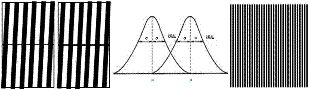
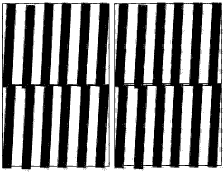
[0057] Example 1: Determine the spot size P = 200um, Λ = 500nm period, 2x2 overlapping tiling interference exposure, translation amount L = 100um, then accurately adjust the included angle Φ = 0.14 degrees, m =, then the interference fringes are aligned with r =L*sinΦ-mΛ=0. The exposure frequency is set to 2000 Hz, and the photolithography time of a 1mx0.4m diffraction grating is <6 hours.

[0058] Also set the spot size P=400um, 2x2 overlapped tiling interference exposure, the translation amount L=200um, precisely adjust the included angle Φ=0.072 degrees, the exposure frequency is 1KHz, and the photolithography time of 1mx0.4m diffraction grating is <3 hours .

Embodiment 2

[0059] Embodiment 2: Determine the angle between the scanning direction and the zero-order phase grating Φ=0.2 degrees, Λ=400nm period, 2x2 overlapped tiling interference exposure, then the scanning translation amount L=114.6um, and the spot size P=229.2 um, r=L*sinΦ-mΛ=0, to achieve interference fringe alignment.

Embodiment 3

[0060] Embodiment 3: Determine the angle between the scanning direction and the zero-order phase grating Φ=0.2 degrees, the spot size is 250um, the translation amount is 125um, M=20, then the zero-order phase grating translation amount is 1.45um, r=L*sinΦ -mΛ=0, to achieve interference fringe alignment.

[0061] In the above example, the movement of the zero-order phase grating will be slightly corrected according to the actual detection error, so that the efficiency of the entire splicing exposure is greatly improved.

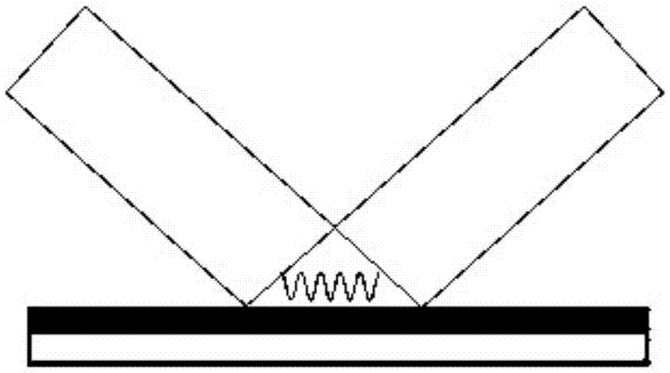
[0062] When using a spot of more than 500um, the objective lens in the projection optics needs to be specially designed and processed to ensure that the numerical aperture NA is higher than 0.5. At the same time, the lens diameter is greater than 20mm and the focal length is less than 20mm to ensure the size of the exposure field of view.


PUM

PropertyMeasurementUnit
lengthaaaaaaaaaa

Abstract

The invention relates to a manufacturing method for a large-dimension diffraction grating and an exposure device thereof. The exposure device comprises two stages of micro modules and a zero-order suppression phase grating; the first-stage micro module is a 4F imaging system and the second-stage micro module is a double-telecentric micro projection interferometric imaging system; the second-stage micro module has a micro multiple larger than that of the first-stage micro module; and an imaging plane of the first-stage micro module forms an input plane of the second-stage micro module; and an output plane of the second-stage micro module forms a recording plane during exposure imaging. The first-stage micro module includes a first Fourier transform lens or lens set and a second Fourier transform lens or lens set. Besides, the zero-order suppression phase grating is arranged between the first Fourier transform lens or lens set and the second Fourier transform lens or lens set. When a stripe position in exposed spot needs to be adjusted, the zero-order suppression phase grating is translated along the direction perpendicular to the grid line, thereby realizing changing of the stripe position in the spot.

Description

technical field [0001] The invention belongs to the field of manufacturing large-scale diffraction gratings, and in particular relates to a method for manufacturing large-scale diffraction gratings by using a local light field splicing process. Background technique [0002] Large-area diffraction gratings play an irreplaceable role in astrophysics, laser physics and other fields. The preparation methods of diffraction gratings include mechanical writing, laser holographic interference and other methods. Among them, the mechanical writing method is generally only suitable for the production of gratings with a large grid line period, and the production accuracy and efficiency are restricted. Laser holographic interferometry splits, expands and reflects the laser beam to form interference fringes in the intersection area of ​​the two expanded beam spots, and record the interference fringes on the photoresist, such as figure 1 shown. After development, ion beam etching and ot...

Claims


Application Information

Patent Timeline
Patent Type & Authority Applications(China)
IPC IPC(8): G02B5/18G03F7/20
CPCG02B5/1857G03F7/2022G03F7/2051
Inventor 陈林森朱鹏飞浦东林楼益民魏国军朱铭杨颖申溯叶燕刘艳花
Owner SUZHOU UNIV
Why Eureka
Try Eureka