Method and device for eliminating splicing seams of splicing wall as well as image system based on splicing wall

A splicing wall and image technology, which is applied to a device for eliminating splicing joints in a splicing wall, in the field of image systems based on splicing walls, can solve the problem of destroying the sealing of the optical path of a box-type display unit, and is not suitable for display background walls to eliminate joint applications and backgrounds. Problems such as non-frontal shooting of the wall

Active Publication Date: 2012-06-20
RUGAO TIANAN ELECTRIC TECH
View PDF2 Cites 13 Cited by
  • Summary
  • Abstract
  • Description
  • Claims
  • Application Information

AI Technical Summary

Problems solved by technology

[0003] However, in the current application of the background display wall, since the entire display splicing wall is spliced ​​by various DLP display units, there is inevitably a gap between the splicing display unit and the splicing display unit. Horizontally speaking, this gap can be controlled within 1 mm, but for the viewers at the TV end, they can still clearly see the larger gap between each splicing display screen. When the camera lens is zoomed in, this gap will be more obvious
[0004] In order to solve this patchwork problem, the currently adopted schemes all use the edge fusion method to form a seamless picture by performing brightness gradient and feathering on

Method used


Image

  • Method and device for eliminating splicing seams of splicing wall as well as image system based on splicing wall
  • Method and device for eliminating splicing seams of splicing wall as well as image system based on splicing wall
  • Method and device for eliminating splicing seams of splicing wall as well as image system based on splicing wall

Examples


Embodiment Construction

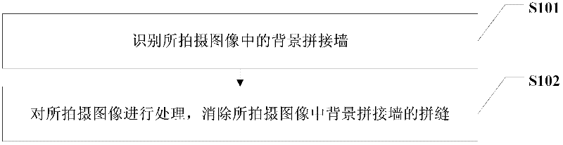
[0036] figure 1 shows a schematic flow chart of an embodiment of the method for eliminating spliced ​​wall splices of the present invention, as figure 1 As shown, it includes the steps:

[0037] Step S101: identifying the background mosaic wall in the captured image;

[0038] Step S102: Process the captured image to eliminate the seams of the background mosaic wall in the captured image.

[0039] Among them, when identifying the background mosaic wall in the captured image in the above step S101, there may be various implementations, for example, it may be by adding a special color or a sign of nailing material to each of the four edges of the mosaic wall , or set 1 to 2 special pixel values ​​at the four corners of the screen, or add at least three prominent marks on the screen edge of the splicing display wall, so that when the camera is shooting, it can be automatically identified by recognizing these special marks The display edge of the background mosaic wall is detect...


PUM


Abstract

The invention provides a method and a device for eliminating splicing seams of a splicing wall as well as an image system based on the splicing wall. The method comprises the following steps: distinguishing a background splicing wall in a shot image; processing the shot image, and eliminating the splicing seams of the splicing wall in the shot image. According to the technical scheme of the invention, show edges of the splicing wall can be distinguished in the image shot by a camera, and the splicing wall in the shot image can be processed to eliminate the splicing seams of the splicing wall in the shot image, thus the splicing seams of a picture output by the display can be effectively eliminated, but the splicing display wall does not need to be processed, the hardware cost can not be increased, and the consistency of pictures with different viewpoints can be realized without the restriction of the viewing angle changes of the camera.

Description

technical field [0001] The invention relates to a method for eliminating seams of a mosaic wall, a device for eliminating seams of a mosaic wall, and an image system based on a mosaic wall. Background technique [0002] With the continuous development and update of LED light source DLP display technology, splicing wall display technology has been widely used. The characteristics of LED light source wide color gamut and bright colors have further deepened the application and development of DLP display technology. At present, it is more popular in the broadcasting industry. It has been used more and more, and the DLP display background wall based on LED light source is mostly used. The host can easily interact with the display background wall. After displaying the content and foreground content such as the host, it is directly output to the user for viewing. [0003] However, in the current application of the background display wall, since the entire display splicing wall is ...

Claims


Application Information

Patent Timeline
IPC IPC(8): G06F3/14G06T3/00G09G5/14
Inventor 江志和刘伟俭杨继禹王浩
Owner RUGAO TIANAN ELECTRIC TECH
Why Eureka
Try Eureka