
Door frames and coverings

a door frame and cladding technology, applied in the field of structural framing and cladding systems, can solve the problems of reducing the service life of cladding, unable to address the issue of cladding, and unable to address the potential for rot or other wood deterioration, so as to achieve limited expansion and contraction

Active Publication Date: 2011-07-05
BAY INDUSTIRES
View PDF73 Cites 41 Cited by
  • Summary
  • Abstract
  • Description
  • Claims
  • Application Information

AI Technical Summary

Benefits of technology

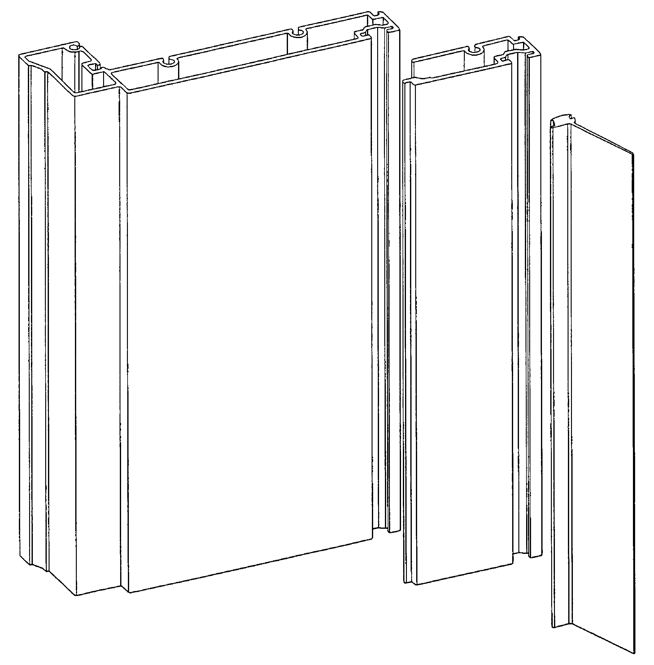
"The present invention is about frames made from fiber reinforced polymeric materials (FRP) such as pultruded fiberglass, which are resistant to changes in temperature, denting, weather, and corrosion. These frames are designed to be attached to building structural members at a doorway rough opening in an exterior wall of a building. The frames have a front, rear, door-facing side, and building-facing side, and are adapted to be attached to the building with fasteners. The frames have a closed perimeter, with an elongate fiber-reinforced pultruded polymeric covering that defines a cavity. The frames are lightweight, moisture-resistant, and have desirable properties such as limited expansion and denting. The invention also includes a kit for making the frames and a building entrance door jamb assembly."

Problems solved by technology

So while wood provides a number of desirable qualities, wood also has some properties which are not desirable in an exterior door through which entrance is gained to the building.
Extruded aluminum, however, is susceptible to wear and tear, for example denting and corrosion.
While cladding obviates the need for periodic repainting, cladding does not address the issue of water wicking up into the frame from the bottom ends of the side jambs of the frame.
Nor does cladding address the potential for rot or other wood deterioration which is typically associated with wicked water.
Further, if the cladding is damaged, attempts at on-site repainting of the aluminum achieve less than desired results in terms of aesthetic appearance.
However, frames made with such materials are typically more expensive, and require more labor to produce and install, and some such structures are subject to undesired levels of expansion and contraction with changes in ambient temperature and / or changes in ambient moisture levels.
Thus, a recognized problem in the conventional art is that residential door frames and cladding require substantial user maintenance to prevent wear and tear, and degradation, and still may not achieve those objectives.
Furthermore, previous door frame kit designs, including side light windows, were relatively expensive to produce and maintain.
The door frames and cladding taught in Boldt '438 have certain disadvantages such as being susceptible to damage after exposure to the elements and from physical impacts by ingress and egress through the doorway, as well as less than desired results from repainting of damaged areas of the aluminum.
Pultruded fiberglass frames exhibit desirably limited expansion and contraction when exposed to changes in ambient temperatures.

Method used


Image

  • Door frames and coverings
  • Door frames and coverings
  • Door frames and coverings

Examples


second embodiment

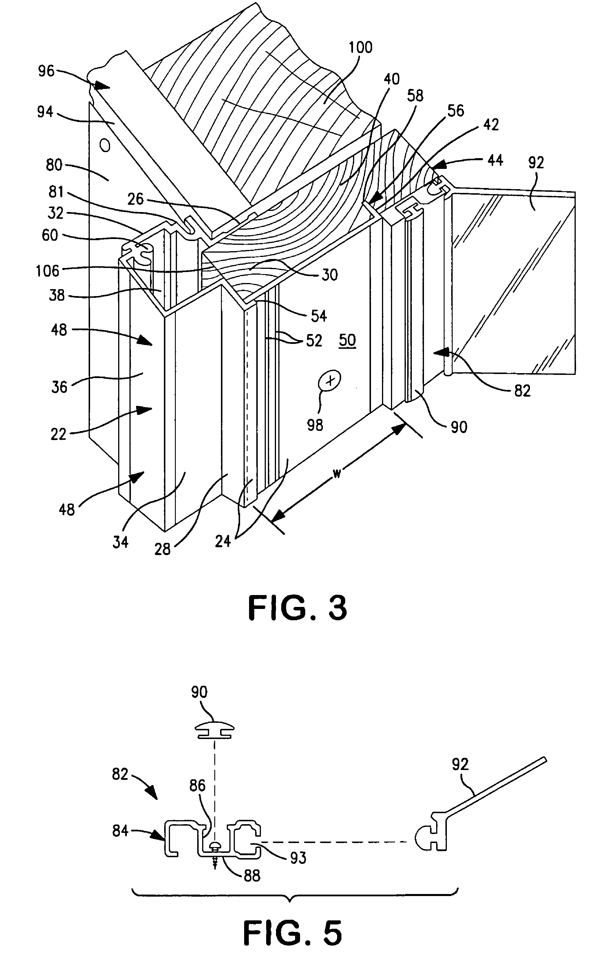
[0089]In a second embodiment illustrated in FIG. 3, fiberglass pultruded structure 22 collectively comprises in combination a first outer fiberglass pultrusion 48 and a second substrate cover pultrusion 50. Substrate cover 50 includes a number of elongate outwardly-facing ridges 52, including an end ridge 54. During assembly of the respective top or side member, one or more ridges 52 can be intentionally broken away from the main body of substrate cover 50 in order to reduce the width “W” of substrate cover 50 to cooperate with the depth of the respective substrate 44. If no such reduction is needed, or after such reduction has been made, the end outwardly facing ridge 52 on the substrate cover then interfaces with a corresponding inwardly-facing ridge on outer pultrusion 48 whereby substrate cover 50 and outer pultrusion 48 are joined together and cooperate to form the two-piece fiberglass pultruded structure 22.

[0090]As with the embodiments of FIG. 2, in the embodiments of FIG. 3,...

third embodiment

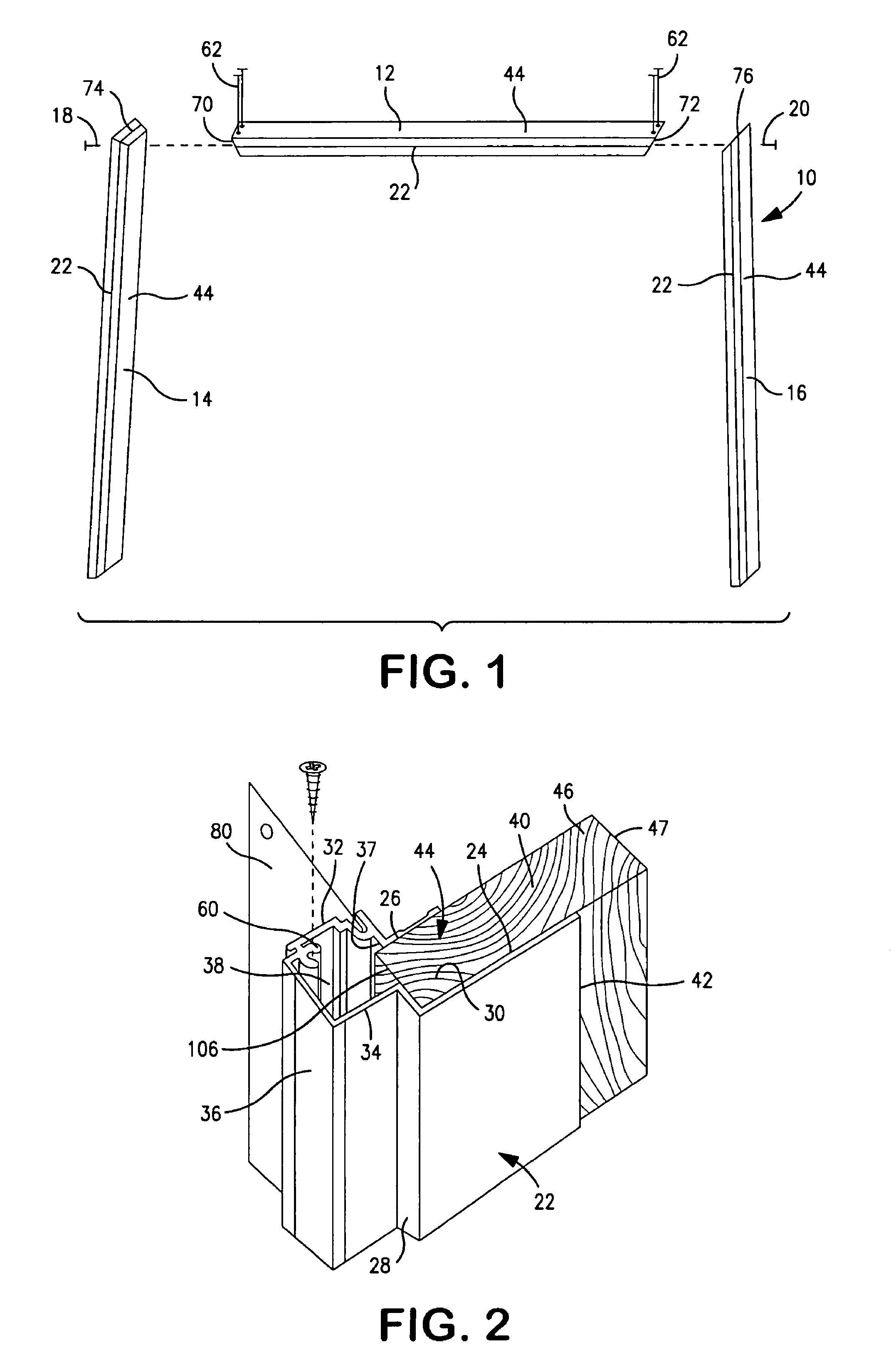
[0093]pultruded fiberglass structure 22 is shown in FIG. 4. In this embodiment, pultruded fiberglass structure 22 has a frontwardly-disposed nosing defined by walls 32, 34, 36, 37, and a rearwardly-disposed jamb body defined by walls 24, 26, 28, 64. Structure 22 is fully enclosed on its front, rear, and side walls, and generally defines the entirety of the structural portion of the jamb. Namely, open edge 40 at the rear of the pultrusion has been closed off. Side wall 26 is the same length as side wall 24, though equal lengths is not a limitation. The opening between side walls 24, 26 is closed off by back wall 64. At least one support web 66 (two support webs are shown) extends across cavity 30 between side walls 24, 26 structurally reinforcing the enclosed pultruded fiberglass structure along the length of enclosed structure 22. Aligned mounting holes (not shown) are provided through side walls 24, 26 at spaced locations along the length of the jamb for mounting the jamb to frame ...


PUM

PropertyMeasurementUnit
thicknessaaaaaaaaaa
anglesaaaaaaaaaa
widthsaaaaaaaaaa

Abstract

Door frames, frame kits, component parts, jamb coverings, and depth extenders, all constructed with fiber reinforced pultruded structures, for entrance doors to buildings, both garage entrance doors and personnel entry doors. Some embodiments have a closed back wall. Others have an open cavity at the back wall to receive a reinforcing substrate. Some embodiments include a pultruded nosing block. Some embodiments comprise a pultruded depth extender, mountable on a jamb base to extend the depth of a door jamb. A mounting finger and a locking stud on the depth extender are mountable in cavities in the jamb base. A depth extender can be used to extend the depth of either a garage door frame or a personnel entry door frame. In an in-swing door frame, a door latch-side abutment surface is located on the side wall of the jamb base.

Description

CROSS REFERENCE TO RELATED APPLICATIONS[0001]This Application is a Non-Provisional of U.S. Provisional Patent Application Ser. No. 60 / 885,121, filed Jan. 16, 2007.BACKGROUND OF THE INVENTION[0002]This invention relates in general to structural framing and cladding systems used in door frames for door assemblies which are used as structural components of buildings. More specifically, the invention relates to frames, frame kits, and jamb substrate coverings made using pultruded fiber reinforced polymeric (FRP), e.g. pultruded fiberglass, structures and wherein frames made from the frame kits, optionally including side light windows, are installed in doorway rough openings which serve as entrance points into a building, and the coverings are installed on door frame substrates.[0003]As used herein, including in the claims which follow, reference to “entry” door frames is directed to doors which are sized and configured to facilitate ingress and egress of people into and out of a buildin...

Claims


Application Information

Patent Timeline
Patent Type & Authority Patents(United States)
IPC IPC(8): E06B1/04
CPCE06B1/30E06B1/32E06B3/302E04F19/0495E06B1/006E06B1/045E06B1/524E06B3/9845E06B2001/622
Inventor BOLDT, GARY L.NOSKOWIAK, TODDCARLSON, TODD A.
Owner BAY INDUSTIRES
Learn More