Mounting for an extension piece of a tall cabinet

Active Publication Date: 2011-07-05
VAUTH SAGEL HLDG
View PDF17 Cites 2 Cited by
  • Summary
  • Abstract
  • Description
  • Claims
  • Application Information

AI Technical Summary

Benefits of technology

It is the object of the invention to provide mounting hardware for a tall-cabinet pullout whereby the pullout can be very

Problems solved by technology

To adjust the furniture fronts, various types of mounting hardware are known, which are expensive to produce, however, and very labor-i

Method used


Image

  • Mounting for an extension piece of a tall cabinet
  • Mounting for an extension piece of a tall cabinet
  • Mounting for an extension piece of a tall cabinet

Examples


Embodiment Construction

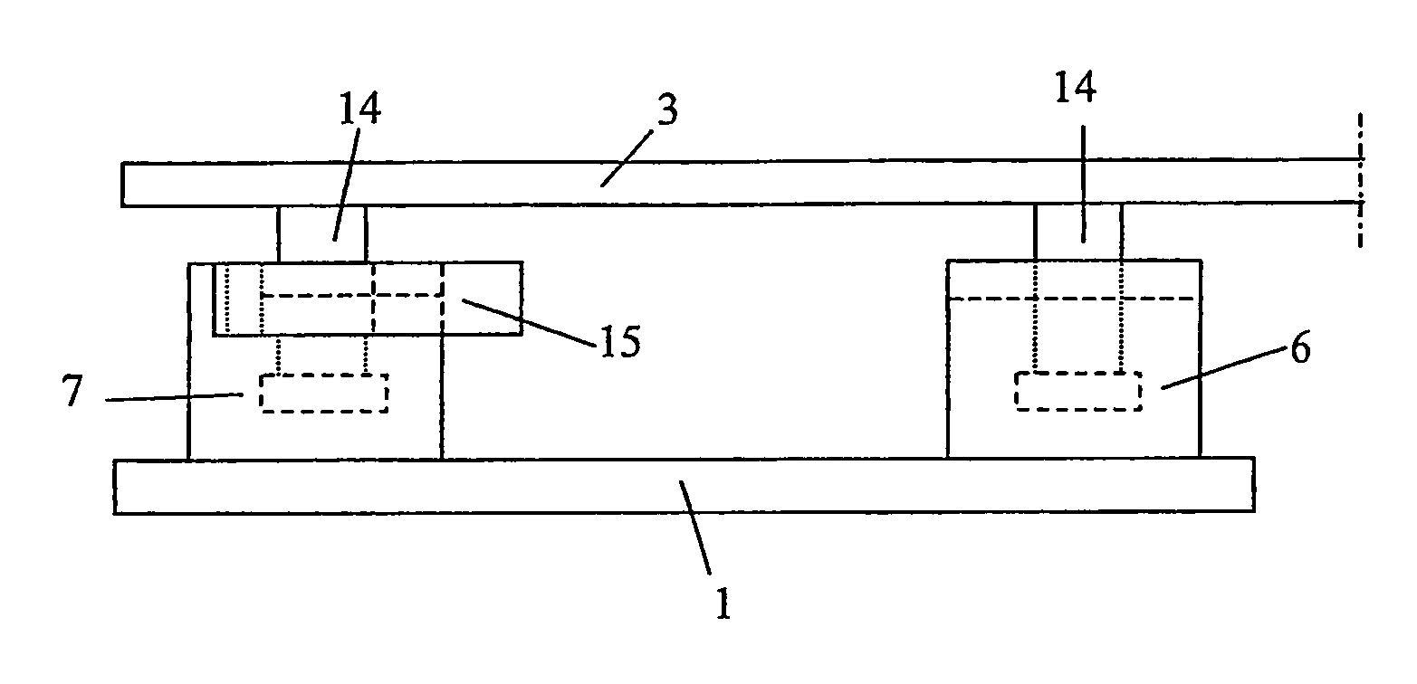
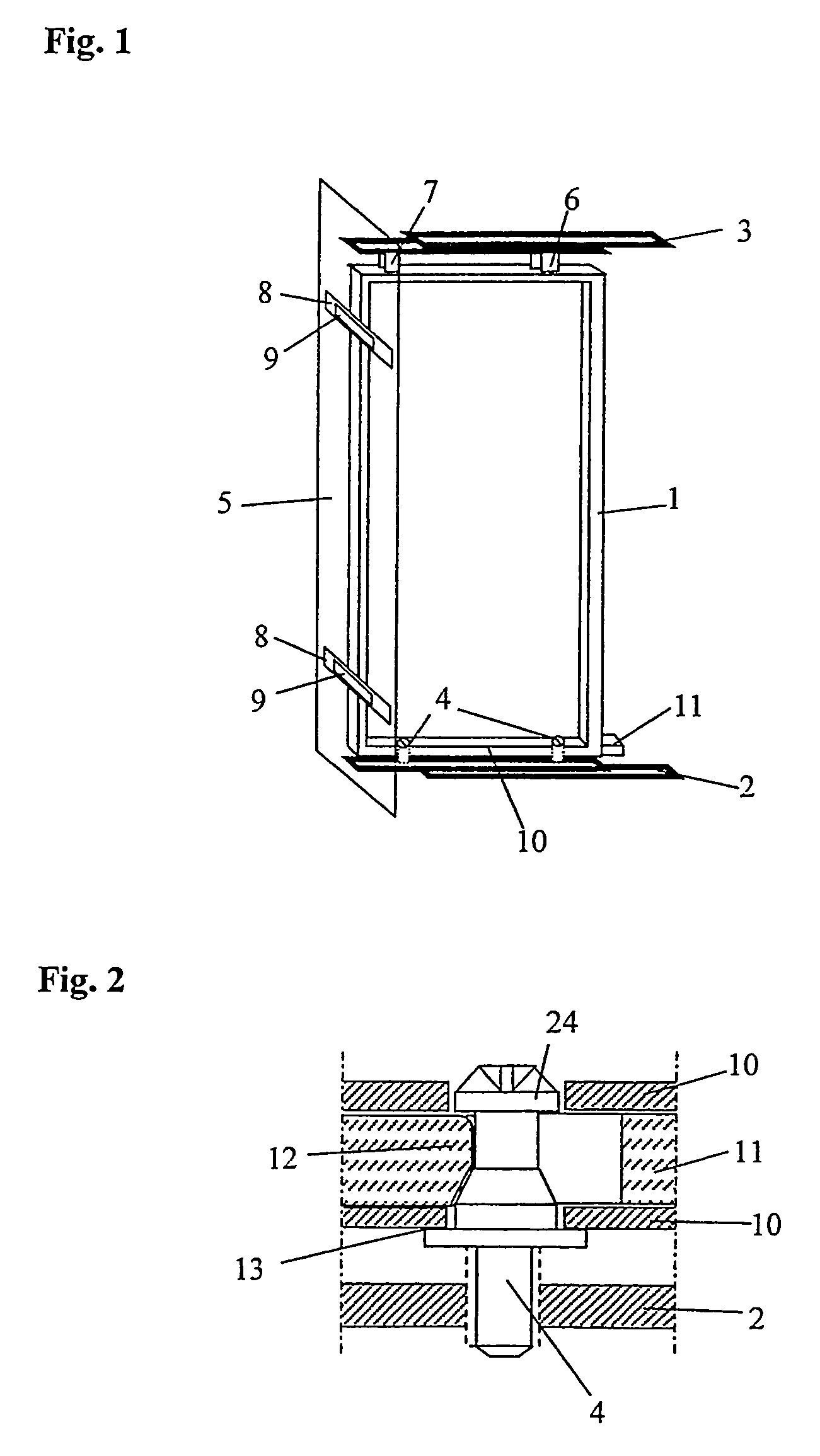
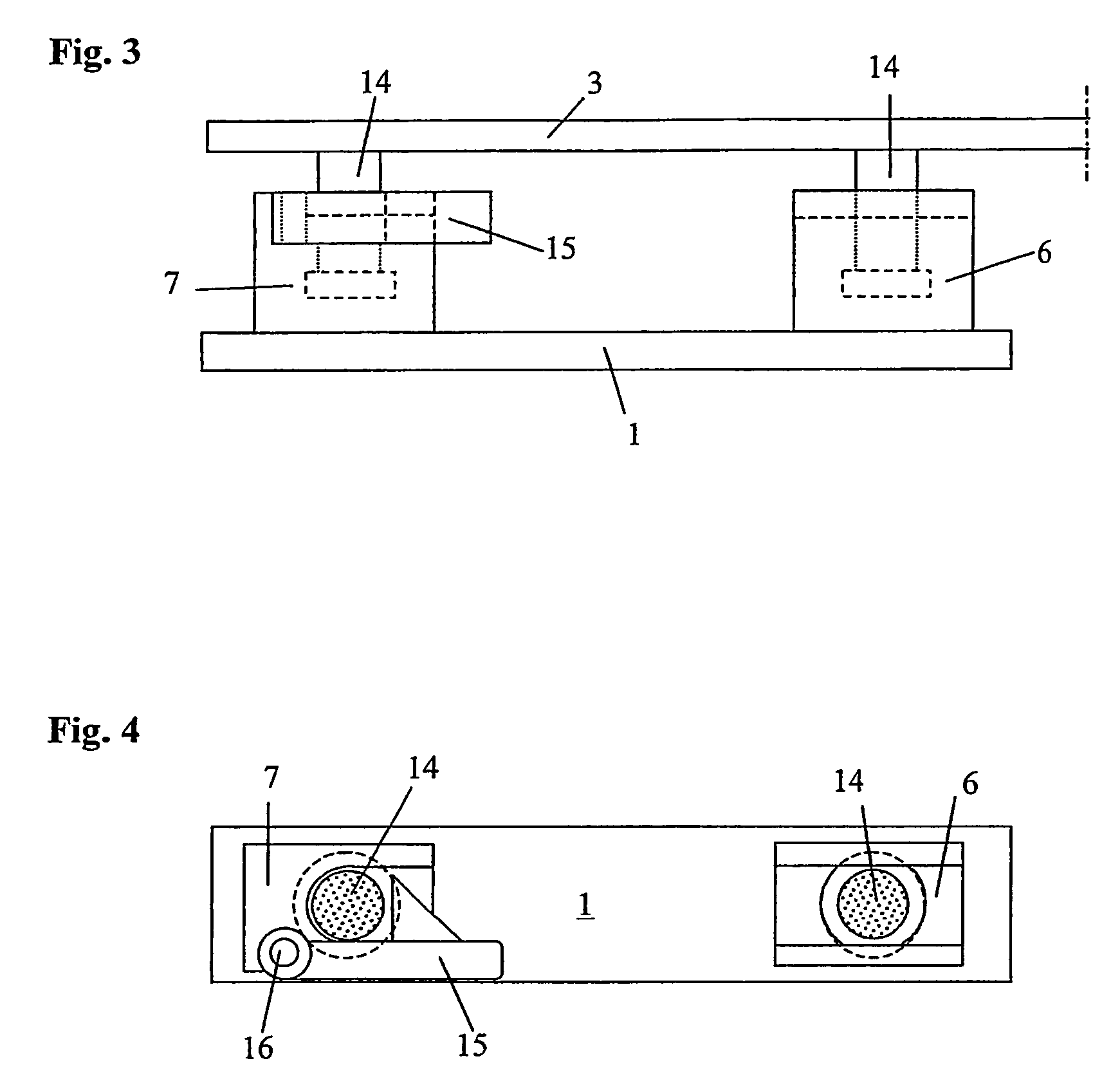
In FIG. 1 the frame 1 is shown in a perspective view with its attachment to the lower telescopic rail 2 and upper telescopic rail 3. The frame 1 rests on the height adjustment screws 4, which are screwed into the lower telescopic rail 2. The locking latch 11 protrudes from the frame 1 and can be pushed in for unlocking. The frame 1 is held at the top by means of the guide block 6 and snap lock 7.

The furniture front 5 is shown transparent. It is attached to the frame 1 by means of the adjustment straps 8 and adjustment blocks 9.

FIG. 2 shows a section through the lower segment 10 of the frame 1 with one of two height adjustment screws 4 aligned with a screw hole of lower telescopic rail 2. The lower segment 10 of the frame 1 rests on the support surface 13. In this position, a spring biases the wedge 12 of locking latch 11 under the head 24 of the screws 4 and in this manner locks the frame in place between the rails (2) and (3). The screws 4 can then be adjusted in the lower telescop...


PUM


Abstract

A mounting for an extension piece of a tall cabinet comprising a front furniture piece (5) which is attached to a vertical, central, strong frame (1). The height of the frame (1) is adjusted on the lower telescopic rail (2) by means of two height-adjustable screws (4) and is locked by means of a locking bolt (11) which is elastically guided in a horizontal manner in the lower frame segment (10).

Description

The invention relates to mounting hardware for a tall-cabinet pullout having a furniture front attached on a vertical central rigid frame, said frame being affixed to an upper and on a lower telescopic rail in such a way that it can be pulled out from the tall cabinet.PRIOR ARTIn a tall-cabinet pullout, also referred to as pharmacy-style pullout or pantry pullout, a central rigid frame supports the baskets or shelves inside the cabinet. Tall-cabinet pullouts of this type with telescopic rails are known, for example, from German utility-model DE 299 06 227.6.In these cabinets, the frame is attached at the top and bottom in each case to a telescopic rail, and the cabinet pullout is pulled into or out from the carcass of the cabinet in this manner. The furniture front of the pullout is attached to the frame and adjustable in such a way that a smooth transition to and flush lines with the adjacent furniture fronts are created. To adjust the furniture fronts, various types of mounting ha...

Claims


Application Information

Patent Timeline
IPC IPC(8): A47B88/00A47B88/04
CPCA47B88/0485A47B88/42
Inventor SAGEL, THOMASSAGEL, CLAUS
Owner VAUTH SAGEL HLDG
Why Eureka
Try Eureka