
Latch assembly for a staple gun

a staple gun and latch technology, applied in the field of latch assembly, can solve the problems of inconvenient use of conventional staple guns, wear and tear of protection devices, and injuring peopl

Inactive Publication Date: 2011-07-19
LIN JUI YUAN
View PDF7 Cites 7 Cited by
  • Summary
  • Abstract
  • Description
  • Claims
  • Application Information

AI Technical Summary

Benefits of technology

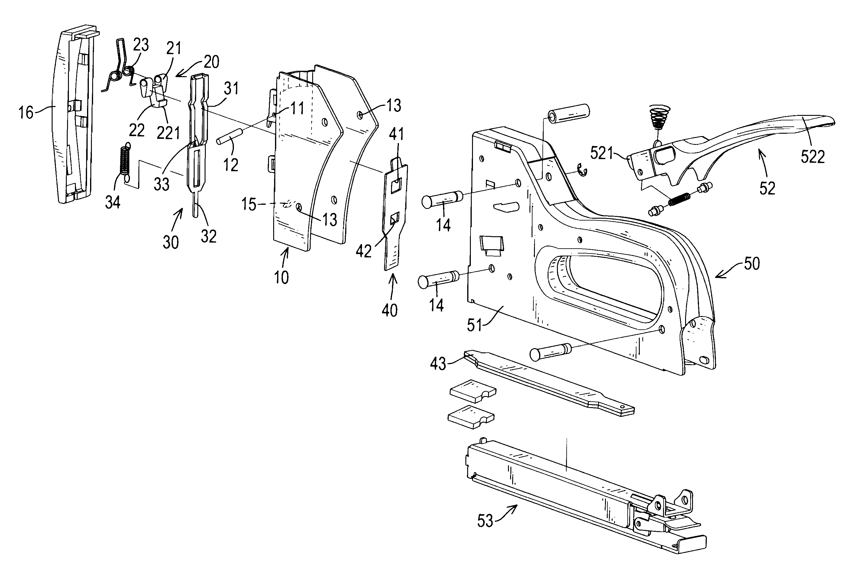
"The present invention provides a latch assembly for a staple gun that can safely and conveniently hold the handle of the staple gun when it is not being used. The latch assembly includes a front cover, a locking element, a pushing element, and a staple driver. The front cover is detachably mounted on the staple gun and has bolt holes and a connecting bolt. The locking element is pivotally mounted on the front cover and has a cam, a locking block, and a torsion spring. The cam is rotatably mounted around the connecting bolt. The locking block is formed with the cam below the connecting bolt. The torsion spring is mounted around the connecting bolt to push the locking block moving backward to the front cover. The pushing element is slidably mounted in the front cover and has a pushing lever and a pressing pin. The pushing lever abuts the at least one cam. The pressing pin extends out of the front cover. The staple driver is mounted slidably between the front cover and the staple gun and has a locking hole, a through hole, and an elastic panel. The locking hole is formed through the staple driver and engages the locking block. The through hole is formed through the staple driver. The elastic panel engages the through hole. The technical effects of the invention are that it provides a convenient and safe way to handle the staple gun when it is not being used, and it ensures the staple driver is securely locked when the staple gun is not in use."

Problems solved by technology

This may be dangerous if a handle of the staple gun is thoughtlessly squeezed, which ejects a staple from the staple gun and may injure someone.
However, the protection device for the conventional staple gun has a complicated structure and locking the handle to the staple gun by the protection device rubbing against the staple gun isn't easy so the conventional staple gun is inconvenient to use.
In addition, the protection device will wear down and will not hold the housing securely after a long time and may get someone hurt.

Method used


Image

  • Latch assembly for a staple gun
  • Latch assembly for a staple gun
  • Latch assembly for a staple gun

Examples


Embodiment Construction

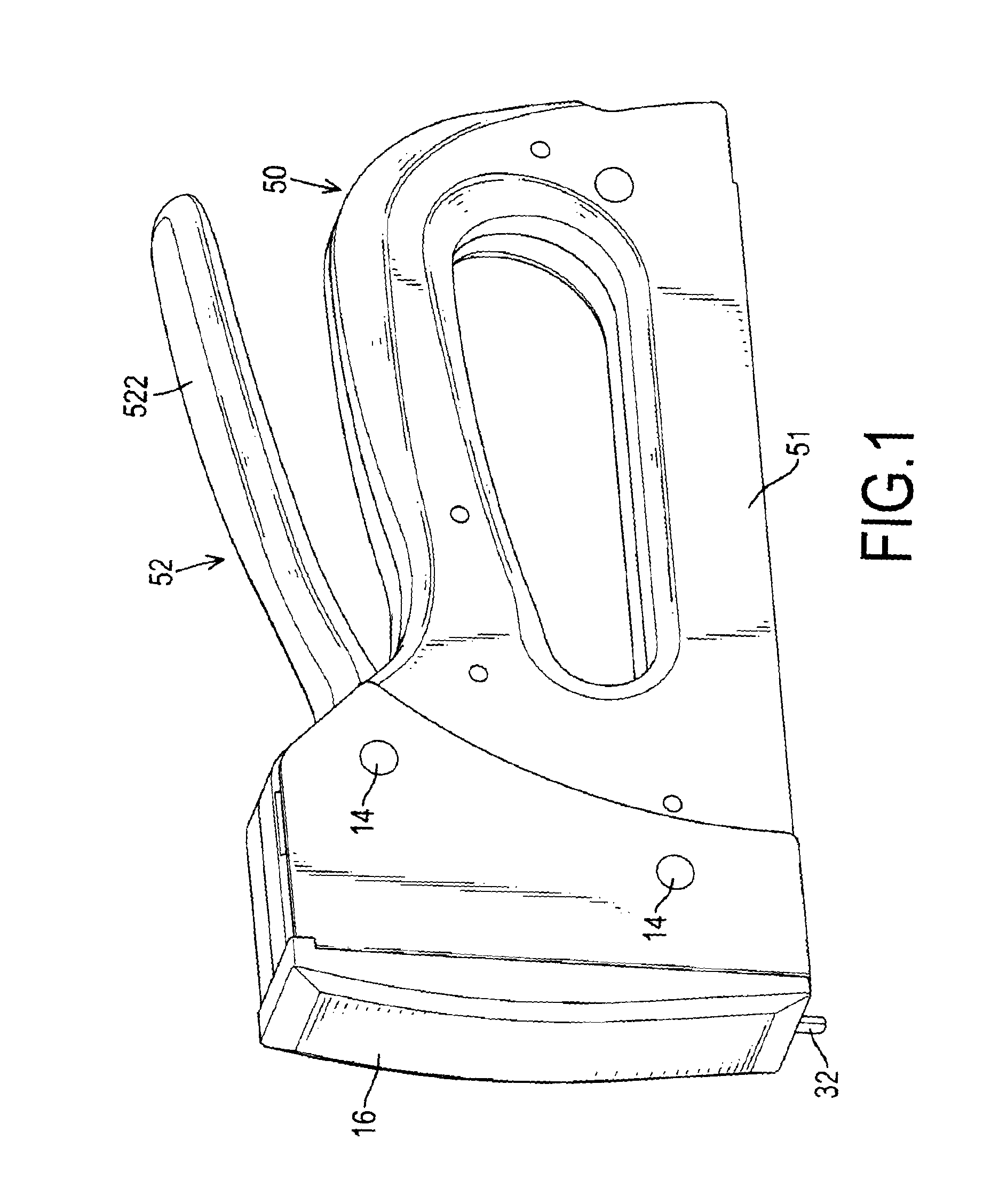
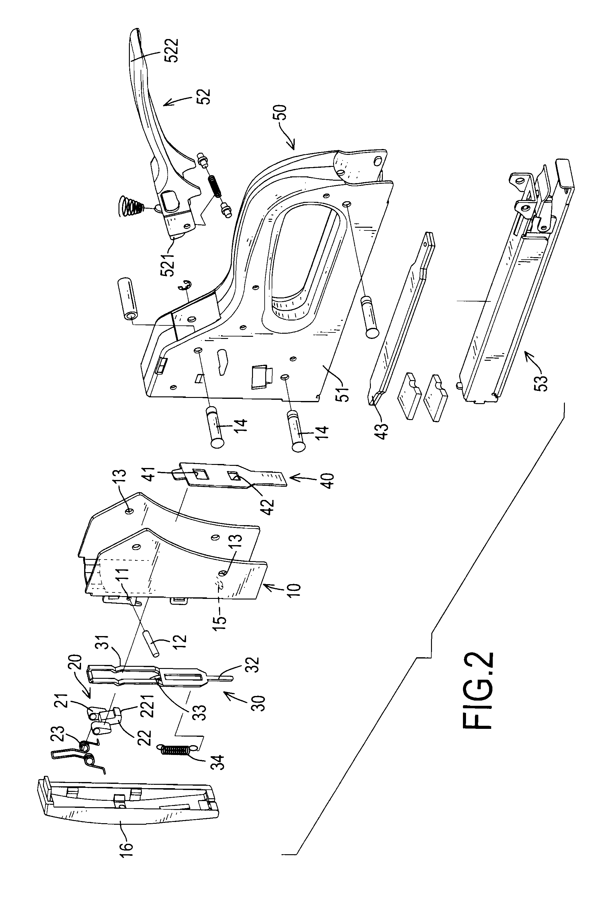
[0014]With reference to FIGS. 1, 2 and 3, a latch assembly in accordance with the present invention is mounted in a staple gun (50) having a housing (51), a handle (52) and a staple magazine (53) and the latch assembly comprises a front cover (10), a locking element (20), a pushing element (30) and a staple driver (40).

[0015]The housing (51) is hollow, may be formed by two half-casings and has a front side, a top edge and a bottom edge.

[0016]The handle (52) is connected pivotally to the housing (51), protrudes from the top edge of the housing (51) and has an acting end (521) and a pressing end (522). The acting end (521) of the handle (52) is pivotally mounted inside the housing (51) and extends to the front side of the housing (51). The pressing end (522) of the handle (52) extends out of the top edge of the housing (51).

[0017]The staple magazine (53) is mounted in the housing (51) at the bottom edge, holds multiple staples and pushes the staples to a front of the staple magazine (...


PUM

PropertyMeasurementUnit
impulsive forceaaaaaaaaaa
speedaaaaaaaaaa
elasticaaaaaaaaaa

Abstract

A latch assembly for a staple gun has a front cover, a locking element, a pushing element and a staple driver. The front cover has a connecting bolt. The locking element is mounted on the front cover and has two cams, a torsion spring and a locking block. The cams and the torsion spring are mounted around the connecting bolt. The pushing element is mounted in the front cover and has a pushing lever and a pressing pin. The pushing lever abuts the cams. The pressing pin extends out of the front cover. The staple driver is mounted in the front cover and has a locking hole, a through hole and an elastic panel. The locking hole is formed through the staple driver and engages the locking block. The latch assembly can hold a handle of the staple gun conveniently and safely when the staple gun is not being used.

Description

BACKGROUND OF THE INVENTION[0001]1. Field of the Invention[0002]The present invention relates to a latch assembly, and more particularly relates to a latch assembly for a staple gun that can hold a handle of the staple gun conveniently and safely when the staple gun is not being used.[0003]2. Description of Related Art[0004]A conventional staple gun is used extensively with decorations, shoemaking and leatherwear and drives staples into objects. Accordingly, the staple is ejected from the staple gun at a high speed. This may be dangerous if a handle of the staple gun is thoughtlessly squeezed, which ejects a staple from the staple gun and may injure someone. Consequentially, conventional staple guns usually have a protection device to hold the handle against the staple gun when the staple gun is not being used to prevent the staples from being shoot from the staple gun.[0005]However, the protection device for the conventional staple gun has a complicated structure and locking the ha...

Claims


Application Information

Patent Timeline
Patent Type & Authority Patents(United States)
IPC IPC(8): B27F7/07
CPCB25C5/0257B25C5/11
Inventor LIN, JUI-YUAN
Owner LIN JUI YUAN
Learn More