Inside wall mounted hanging rods

a technology of hanging rods and wall plates, which is applied in the direction of manufacturing tools, curling suspension devices, gymnastics, etc., can solve the problems of rods falling to the floor, and achieve the effect of pleasing appearance and simple installation

Inactive Publication Date: 2011-08-16
SOURCE GLOBAL ENTERPRISES
View PDF12 Cites 27 Cited by
  • Summary
  • Abstract
  • Description
  • Claims
  • Application Information

AI Technical Summary

Benefits of technology

[0005]The present invention overcomes the aforementioned shortcomings of prior art inside rod mounting arrangements by providing for simple installation, security, and a pleasing appearance. More particularly the present invention provides a support rod having two telescoping sections slidably connected with respect to one another and sharing a common longitudinal axis, each of the sections having an end comprising a rod threaded connector with an axis, a pair of receivers, each of the receivers having an axial open bore extending between a wall mountable end of the receiver and an opposite rod receiving end of the receiver and having a receiver threaded connector with an axis, the receiver threaded connector being complementary to one of the rod threaded connectors, a fastener for mounting each receiver on a respective one of two facing walls with the receiver axes in horizontal alignment, one of the rod threaded connector and the receiver threaded connector being a male connector with its threads facing away from its axis, the other of the rod threaded connector and the receiver threaded connector being a female connector having a hollow bore in which its threads face toward its axis, each fastener for mounting each receiver being at least partially disposed within the bore of its respective receiver for being hidden from view when one of the rod threaded connectors is mated with the receiver threaded connector of the receiver.

Problems solved by technology

Moreover, such mounting schemes generally require that the rod be of fixed length carefully cut to the right size as the ends of a telescoping adjustable rod are subject to being withdrawn from their seats, thereby causing the rod to fall to the floor.

Method used


Image

  • Inside wall mounted hanging rods
  • Inside wall mounted hanging rods
  • Inside wall mounted hanging rods

Examples


Embodiment Construction

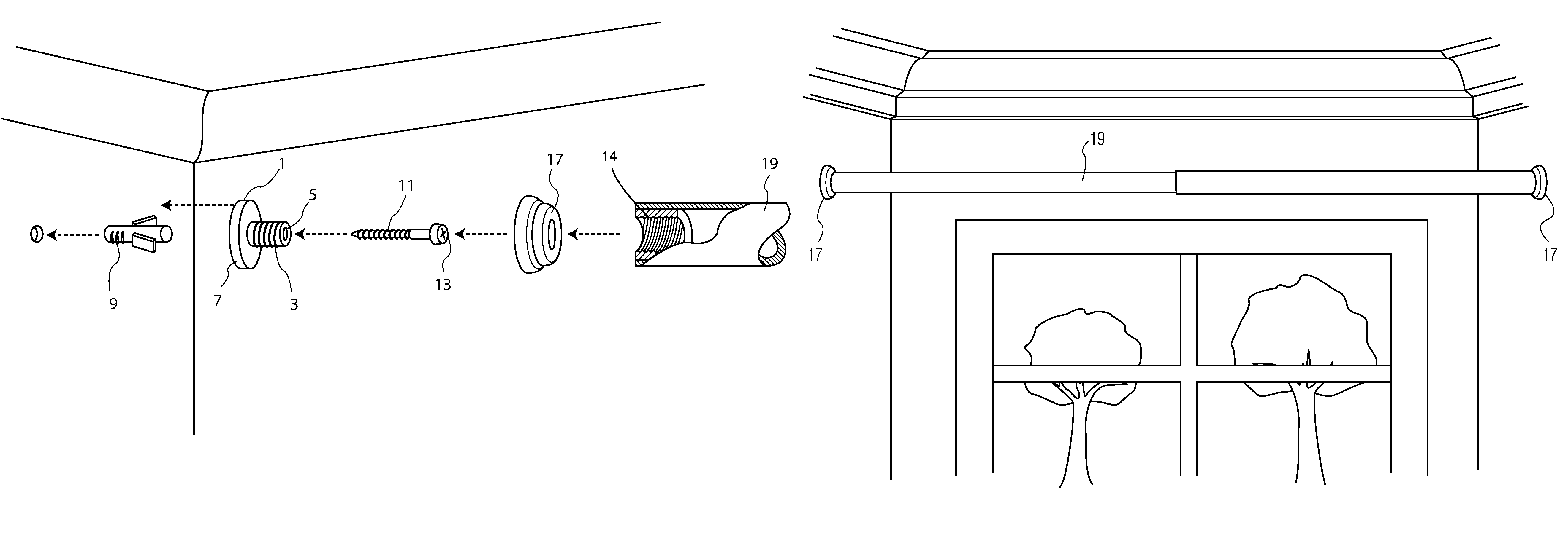
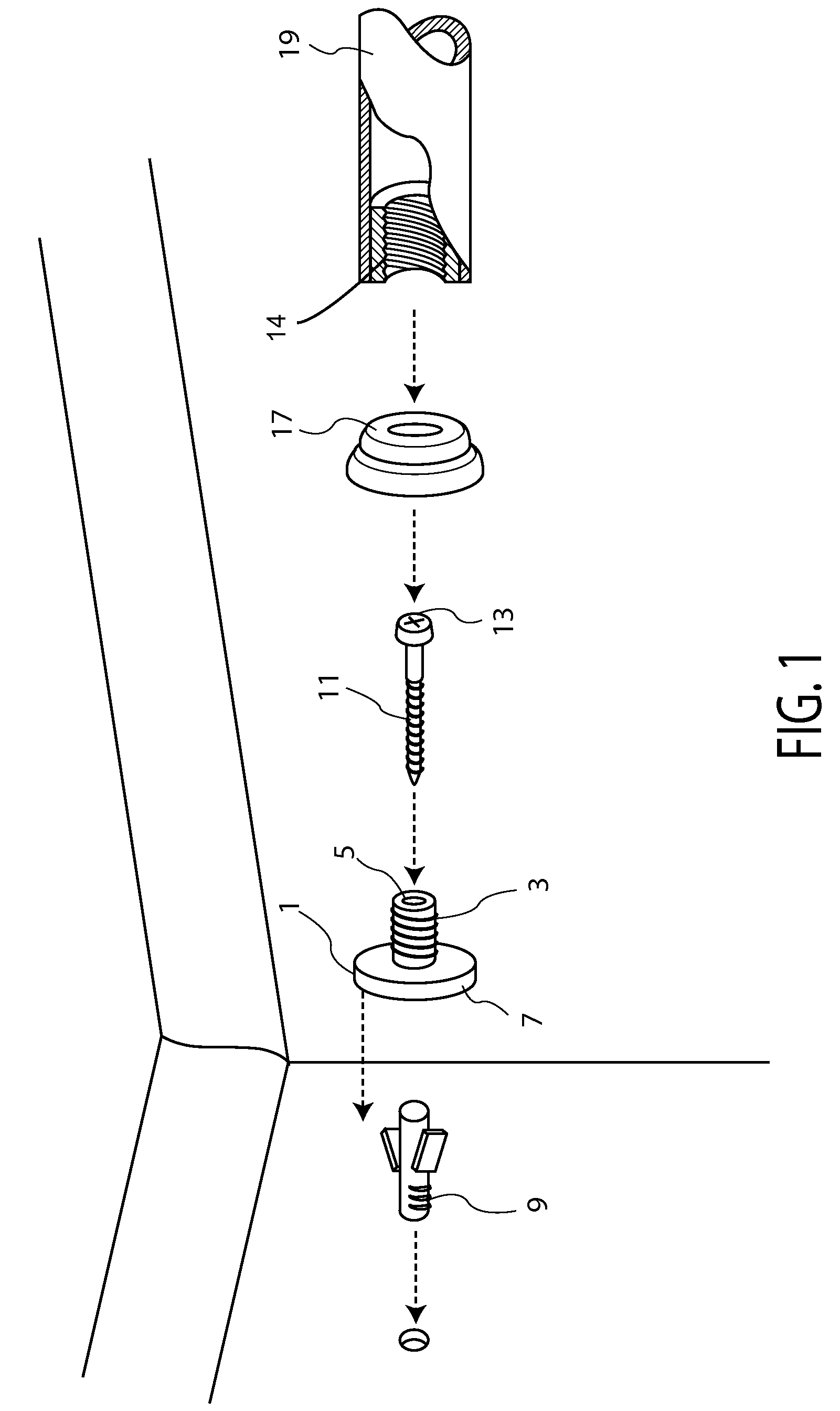
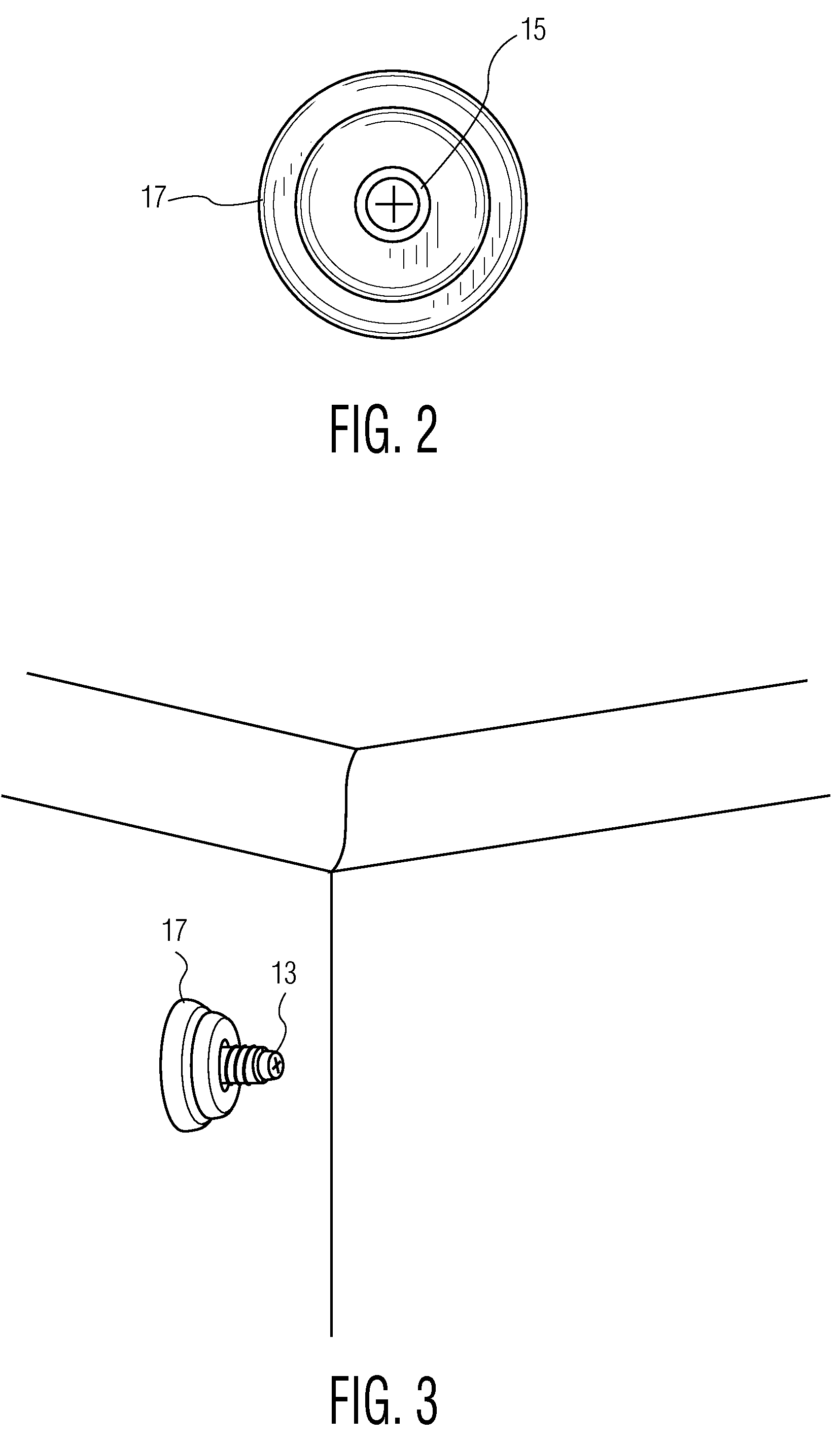
[0016]Referring now to FIG. 1 of the drawings, there is shown a receiver 1 having a threaded connector in the form of a stud 3 with male threads and a central axial open bore 5 extending between a wall mountable end of the receiver 1 and an opposite rod receiving end of the receiver 1 in communication with a central aperture 6 in a circular flange 7 from which the stud 3 extends. An optional anchor 9 adapted to be driven through a hole drilled in a wall is provided for receiving the shank of a fastener which, in the preferred embodiment of the invention, is a screw 11, but which can also be a nail or other fastener having a shank and a head as will be known to those skilled in the art. The shank of the screw 11 is passed through the bore 5 and aperture with the end of the screw 11 distal from its shank penetrating the wall. Where the axis of the receiver 1 is in alignment with a stud in the wall, the anchor 9 need not be used and the screw 11 may be driven through the wall into the ...


PUM


Abstract

A support rod for curtains and the like has telescoping sections the ends of which are threaded for being screwed onto respective receivers mountable on facing walls in axial alignment. The receivers are fixed to the walls by fasteners which are concealed within the bore of at least one of the rod section or its mating receiver. A decorative flange may be mounted between each receiver and its respective rod section.

Description

BACKGROUND OF THE INVENTION[0001]The present invention is directed to the mounting of rods between facing walls. Such rods are commonly used in living rooms for hanging decorative curtains and draperies, in bath rooms for hanging shower curtains, and in closets for hanging clothing. Such rods of sufficient strength may also be mounted in hallways and alcoves for use in exercise, e.g., chinning rods.[0002]More specifically the present invention provides a secure mounting of the opposite ends of an adjustable rod between opposing walls while maintaining an aesthetically pleasing appearance.[0003]It is know in the art to mount rods between walls for hanging various articles. Tension rods employ two telescoping sections of a rod which are urged axially apart by one or more springs. A device for securing the rod to the walls may be mounted on the ends of the rod, e.g., a rubber pad or a suction cup. Because such rods must rely wholly on friction between their ends and the adjacent walls,...

Claims


Application Information

Patent Timeline
Patent Type & Authority Patents(United States)
IPC IPC(8): A47H1/08
CPCA47H1/022A47H1/102Y10T16/35Y10S16/41
Inventor GOLDSTEIN, ALLAN
Owner SOURCE GLOBAL ENTERPRISES
Why Eureka
Try Eureka