Method and device for dynamometer testing of a motor vehicle and vehicle components

a technology for motor vehicles and vehicle components, applied in the direction of engine testing, structural/machine measurement, instruments, etc., can solve the problems of large electrical installation, over-complexity, and inability to allow full measurement freedom of applications

Active Publication Date: 2011-08-23
ROTOTEST INT
View PDF11 Cites 24 Cited by
  • Summary
  • Abstract
  • Description
  • Claims
  • Application Information

AI Technical Summary

Problems solved by technology

Roller type dynamometers equipped with large rollers that support vehicle wheels are previously known, but this kind of appliances does, however, not allow full measurement freedom.
These two latter constructions are overly complex, require extensive electrical installation, require fixed installation sites and are not particularly flexible.
Thorough accurate testing of such vehicles has not been possible with solutions according to the background art.
In this connection it should be noted that erroneous torque application of the testing system might seriously damage the transmission system of the vehicle, because if applied torque differs too much from what is intended by the vehicle manufacturer, too much torque has to be re-directed inside the vehicle transmission, for example over a viscous coupling, which in serious cases can result in complete failure of the system.

Method used


Image

  • Method and device for dynamometer testing of a motor vehicle and vehicle components
  • Method and device for dynamometer testing of a motor vehicle and vehicle components
  • Method and device for dynamometer testing of a motor vehicle and vehicle components

Examples


Embodiment Construction

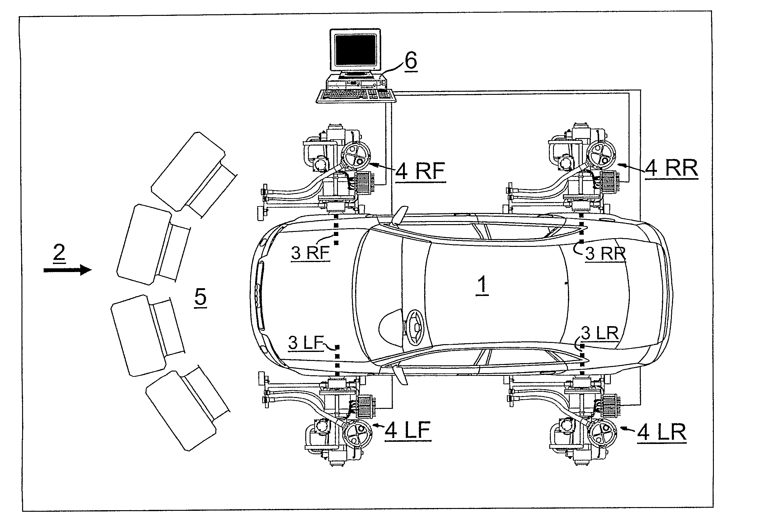
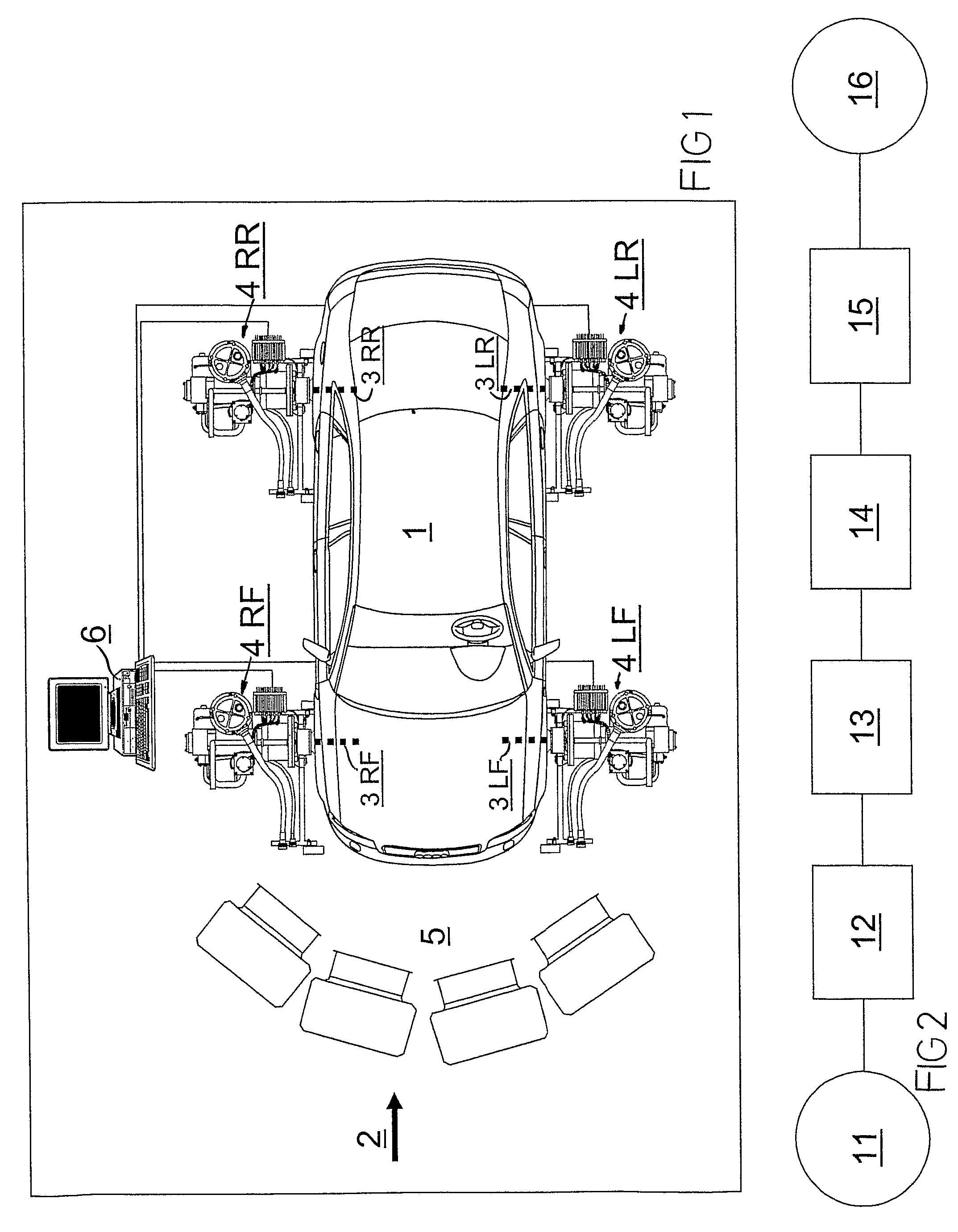
[0036]In FIG. 1, a vehicle 1 is in the process of being tested with a device according to the invention, generally indicated with 2.

[0037]Four dynamometer test units 4LF, 4RF, 4LR and 4RR are directly connected to four drive shafts of the vehicle 1 which is a four-wheel drive vehicle. The shafts are indicated with 3LF, 3RF, 3LR and 3RR. LF=left front, RF=right front, LR=left rear and RR=right rear.

[0038]Each test unit 4LF, 4RF, 4LR and 4RR includes a torque sensor (according to the background art) in order to obtain torque values during operation of the system. A rotational speed sensor (not shown) is also provided for each drive shaft.

[0039]A cooling unit 5 including a number of fans, serves to cool hydraulic fluid that has been heated because of throttling the flow during braking, by applying braking torque over the individual test units 4LF, 4RF, 4LR and 4RR. The cooling unit 5 can also be connected so as to produce a simulated air stream corresponding to the relative air movemen...


PUM


Abstract

A method and a device for dynamometer testing of a motor vehicle, having a front end and a rear end and a right side and a left side, as seen in a driving direction, and / or vehicle components, by measuring torque and rotational speed on drive shafts of the vehicle. A braking torque is applied to each one of the shafts by individual hydraulic dynamometer test units by throttling hydraulic fluid flows. The braking torque is adjustable for each individual one of the drive shafts such that a resulting individual rotational speed for that shaft corresponds to a virtual vehicle speed when driving the motor vehicle on a road, compensated with a slip value.

Description

[0001]This is a national stage of PCT / SE07 / 000478 filed May 16, 2007 and published in English, which has a priority of Sweden no. 0601087-0 filed May 16, 2006, hereby incorporated by reference.FIELD OF THE INVENTION[0002]This invention concerns a method and a device for dynamometer testing of a motor vehicle and vehicle components according to the respective preambles of claims 1 and 12.BACKGROUND OF THE INVENTION[0003]U.S. Pat. No. 4,669,318 (Ångström) concerns an apparatus for dynamometer testing of motor vehicles, wherein load absorbing means in the form of a hydrostatic pump assembly has an input shaft for engagement with a drive shaft of a vehicle to be tested. Sensor means are arranged so as to allow measuring the torque from the vehicle drive shaft. Typically, in a vehicle having two wheel drive, each drive shaft is connected to an individual apparatus of this kind, whereby a total effective torque from the vehicle can be accurately measured.[0004]The apparatus according to t...

Claims


Application Information

Patent Timeline
Patent Type & Authority Patents(United States)
IPC IPC(8): G01M17/00
CPCG01M17/0072G01L3/20
Inventor ENGSTROM, CHRISTIAN
Owner ROTOTEST INT
Why Eureka
Try Eureka