Fixing device

a fixing device and fixing plate technology, applied in the direction of washstands, cycle equipment, light support devices, etc., can solve problems such as difficulty in operating the vehicle, and achieve the effect of preventing difficulty in operation and preventing possible interference with any surrounding member

Active Publication Date: 2011-08-30
CATEYE
View PDF37 Cites 4 Cited by
  • Summary
  • Abstract
  • Description
  • Claims
  • Application Information

AI Technical Summary

Benefits of technology

[0007]An object of the present invention is to provide a fixing device for attaching a prescribed component, which prevents difficulty in operation of a vehicle such as a bicycle and prevents possible interference with any surrounding member.
[0011]In the structure described above, by positioning the pin on the one end or the other end of the elongate hole, it is possible to establish engagement of the second member by the first member or to release the engagement. If the engagement of the second member by the first member is released, the second member may be rotated with respect to the first member and, therefore, an angle of component to be attached to the second member can be adjusted. When the second member is engaged with the first member, the component can be held at a prescribed angle. Specifically, the fixing device prevents difficulty in operation of the vehicle such as a bicycle and prevents possible interference with surrounding members.
[0016]As described above, according to the present invention, a fixing device for attaching a prescribed component is provided, which can prevent difficulty in operation of the vehicle such as a bicycle and prevent interference with surrounding members.

Problems solved by technology

This may lead to a difficulty in operating the vehicle such as a bicycle, or lead to interference with other members located therearound.

Method used


Image

  • Fixing device
  • Fixing device
  • Fixing device

Examples


Embodiment Construction

[0046]In the following, an embodiment of the present invention will be described. It is noted that the same or corresponding portions are denoted by the same reference characters, and their descriptions may not be repeated.

[0047]In the embodiments described in the following, descriptions of numbers, amounts and the like are not intended to limit the scope of the invention unless otherwise specified. Further, in the embodiments below, each component is not always necessary, unless otherwise specified.

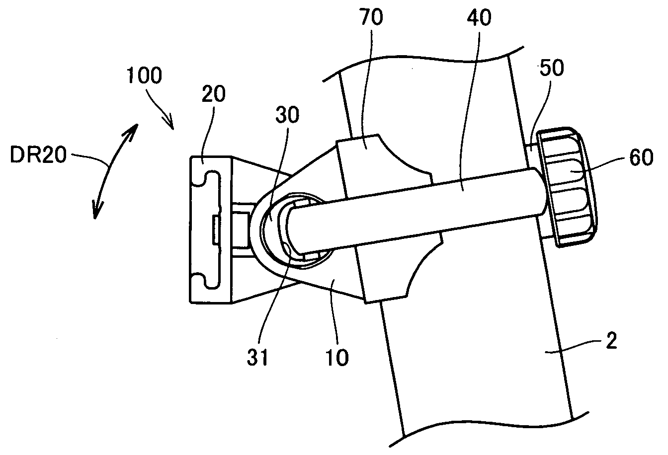
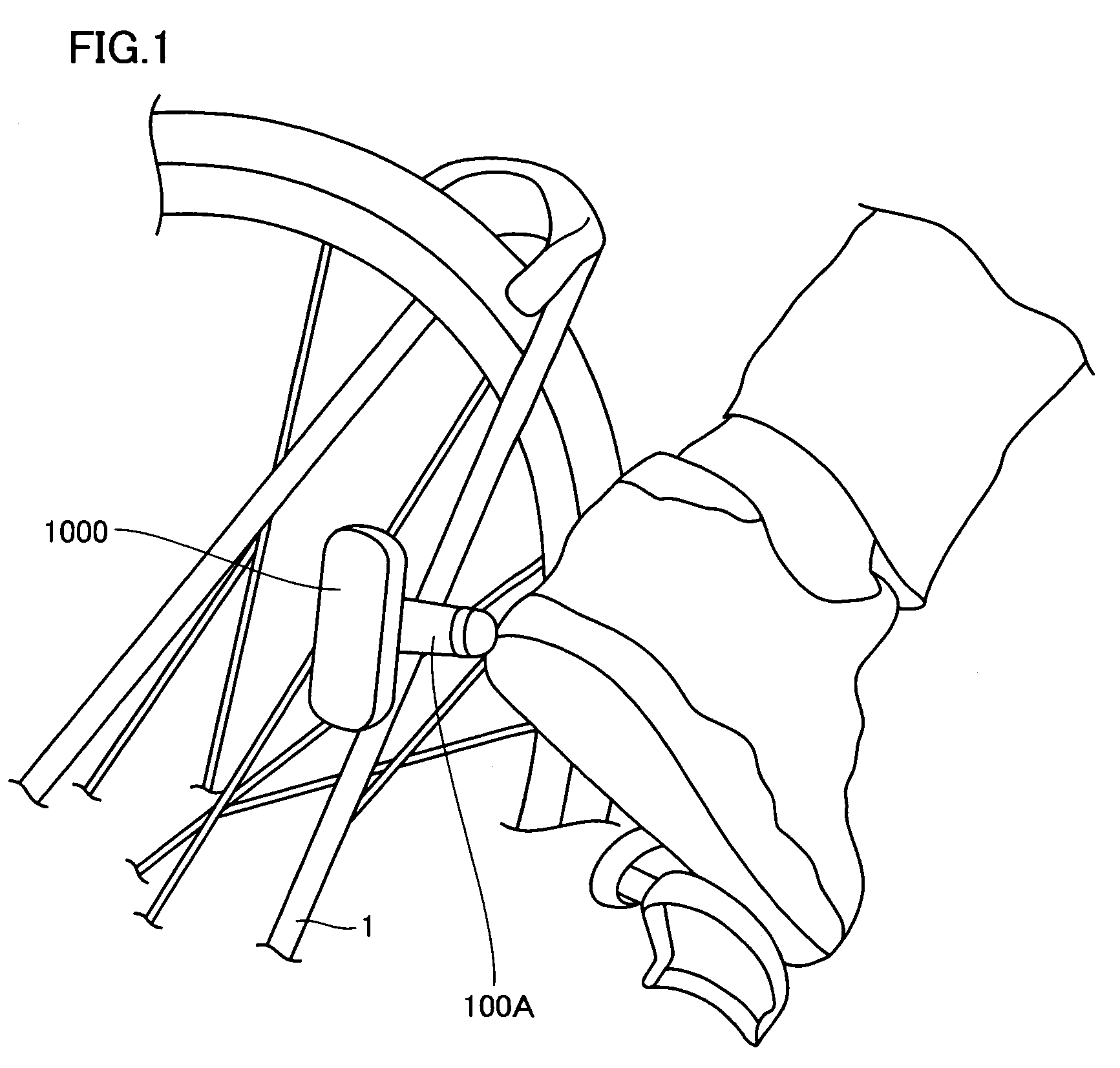
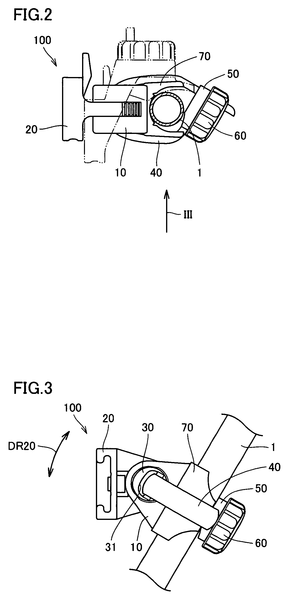
[0048]The “fixing device” in accordance with the present invention is for fixing a prescribed component on a prescribed pipe, and the “prescribed component” and the “prescribed pipe” may be any of various and many components and pipes. In the typical example described below, the “prescribed pipe” is a bicycle frame, and the “prescribed component” may be a tail light, a reflector, a head lamp or the like to be fixed thereon. The “prescribed component” and the “prescribed pipe”, however, a...


PUM


Abstract

A fixing device for a bicycle includes a base, a bracket member, a pin and a band. When fastening of the band is loosened, the bracket member comes to be rotatable in a direction of an arrow DR20 with respect to the base, allowing adjustment of a component angle. When fastened to the pipe by the belt, the base and the bracket member are engaged with each other and held in the engaged state, so that bracket cannot be rotated in a direction of an arrow DR20 with respect to the base.

Description

BACKGROUND OF THE INVENTION[0001]1. Field of the Invention[0002]The present invention relates to a fixing device and, more specifically, to a fixing device for fixing a prescribed component on a prescribed pipe.[0003]2. Description of the Background Art[0004]A fixing device for fixing a prescribed component on a prescribed pipe has been conventionally known. An example of such a fixing device is described in Japanese Patent Laying-Open No. 2006-349164 (Patent Document 1).[0005]The fixing device described in Patent Document 1 can be fixed on a prescribed pipe of a bicycle. Here, a prescribed component is fixed on a bracket (41), and by turning a knob (43), a clamp band (42) is tightly fastened around a handle bar or the like.[0006]In the fixing device described in Patent Document 1, however, bracket (41) cannot be turned about an axis that extends orthogonal to the pipe. This may lead to a difficulty in operating the vehicle such as a bicycle, or lead to interference with other membe...

Claims


Application Information

Patent Timeline
Patent Type & Authority Patents(United States)
IPC IPC(8): F16L3/08
CPCB62J6/00B62J11/00Y10T24/14B62J6/20B62J6/04B62J6/03
Inventor UEDA, TAKASHIOKUDA, YOJI
Owner CATEYE
Why Eureka
Try Eureka