
Integrated circuit package system with bump pad

a technology of integrated circuit and package system, which is applied in the direction of electrical apparatus, semiconductor device details, semiconductor/solid-state device devices, etc., can solve the problems of long time-consuming and laborious, limited integration circuit density,

Active Publication Date: 2011-08-30
JCET SEMICON (SHAOXING) CO LTD
View PDF9 Cites 19 Cited by
  • Summary
  • Abstract
  • Description
  • Claims
  • Application Information

AI Technical Summary

Benefits of technology

This solution improves the reliability and stress distribution of conductive bumps, reduces stress concentration, and supports high-volume wafer-level manufacturing, aligning with the need for cost reduction and performance enhancement in integrated circuit packaging.

Problems solved by technology

Integrated circuit density continues to be limited by the “real estate” available for mounting individual integrated circuits on a substrate.
A number of problems have arisen when reducing size but maintaining big bumps on redistribution layers for wafer level chip scale packages including early failures.
Solutions to these problems have been long sought but prior developments have not taught or suggested any solutions and, thus, solutions to these problems have long eluded those skilled in the art.

Method used


Image

  • Integrated circuit package system with bump pad
  • Integrated circuit package system with bump pad
  • Integrated circuit package system with bump pad

Examples


Embodiment Construction

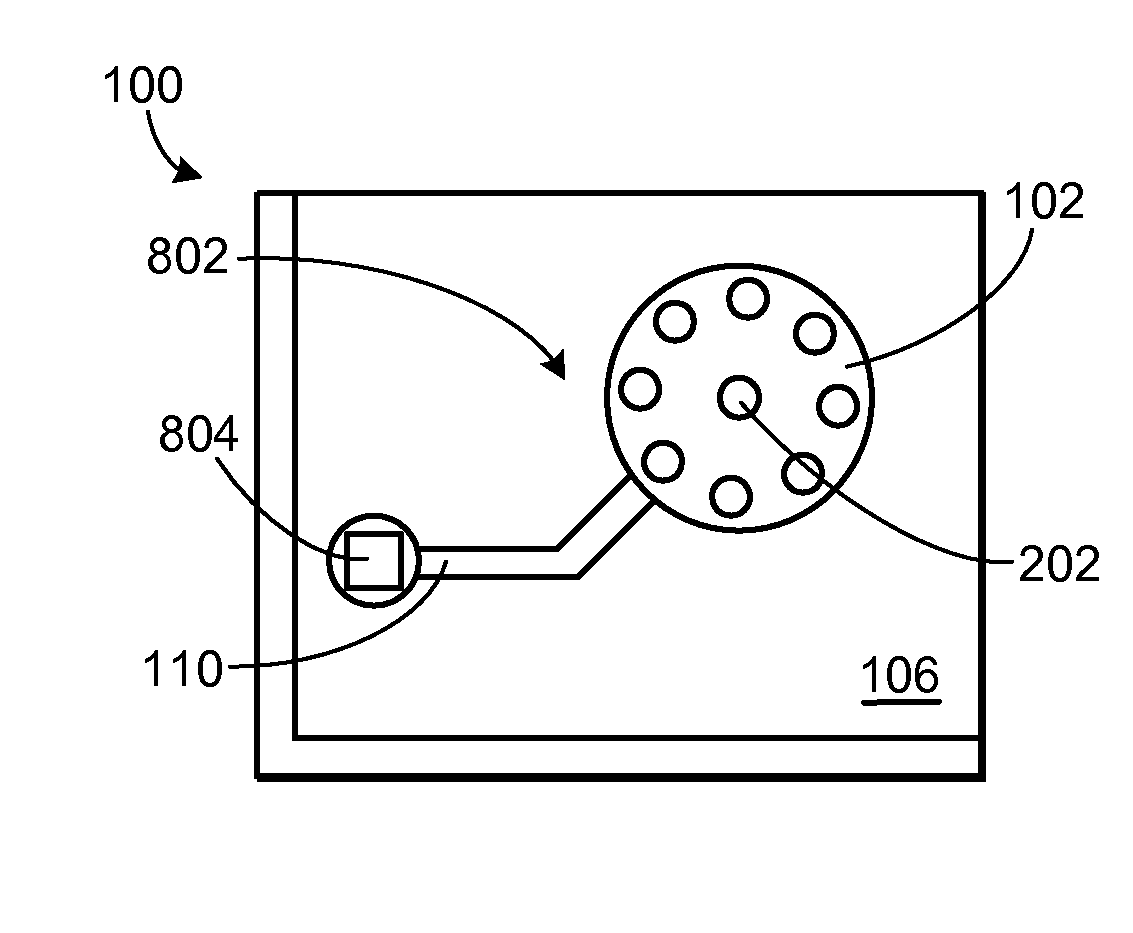
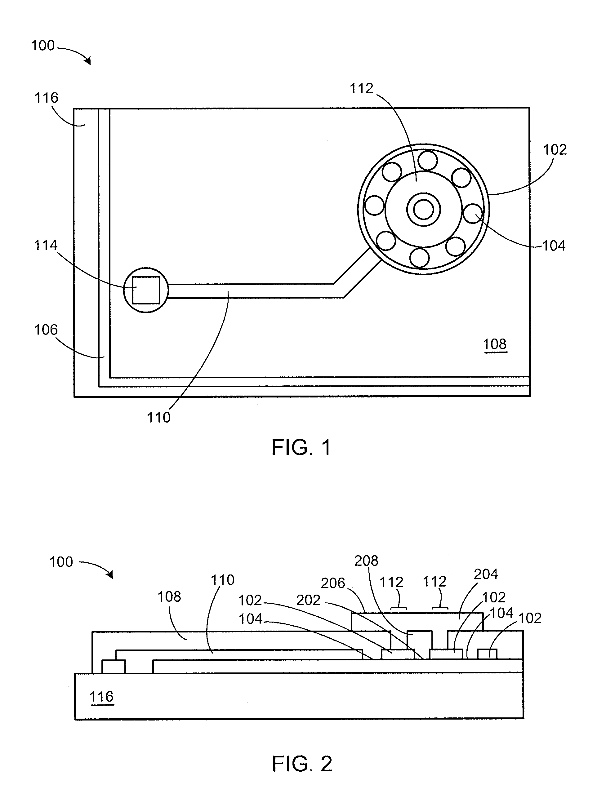
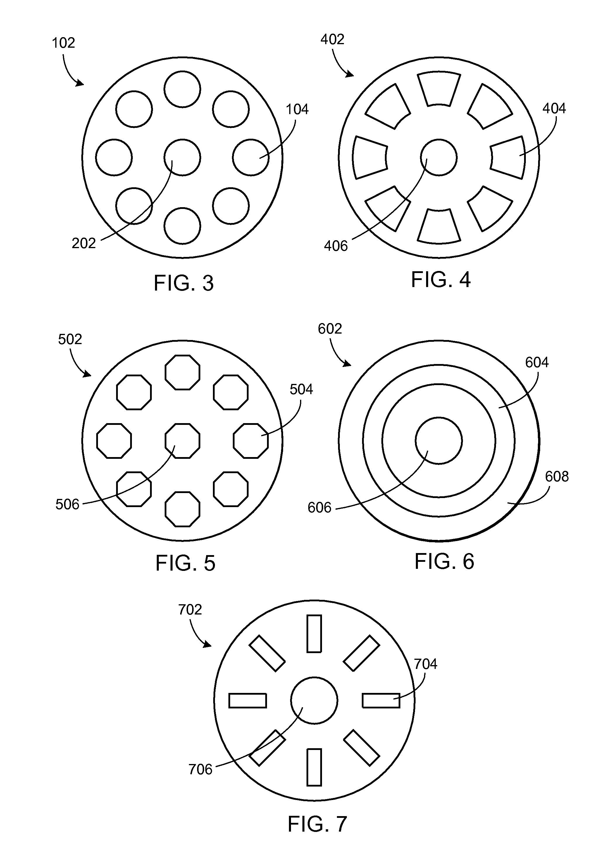
[0030]The following embodiments are described in sufficient detail to enable those skilled in the art to make and use the invention. It is to be understood that other embodiments would be evident based on the present disclosure, and that system, process, or mechanical changes may be made without departing from the scope of the present invention.

[0031]In the following description, numerous specific details are given to provide a thorough understanding of the invention. However, it will be apparent that the invention may be practiced without these specific details. In order to avoid obscuring the present invention, some well-known circuits, system configurations, and process steps are not disclosed in detail. Likewise, the drawings showing embodiments of the system are semi-diagrammatic and not to scale and, particularly, some of the dimensions are for the clarity of presentation and are shown greatly exaggerated in the drawing FIGs. Where multiple embodiments are disclosed and descri...


PUM


Abstract

An integrated circuit package system includes an integrated circuit, and forming a patterned redistribution pad over the integrated circuit.

Description

CROSS-REFERENCE TO RELATED APPLICATION(S)[0001]This application claims the benefit of U.S. Provisional Patent Application Ser. No. 60 / 596,975 filed Nov. 2, 2005.TECHNICAL FIELD[0002]The present invention relates generally to integrated circuit packages, and more particularly to integrated circuit package systems.BACKGROUND ART[0003]Integrated circuit density continues to be limited by the “real estate” available for mounting individual integrated circuits on a substrate. Even larger form factor systems, such as PC's, compute servers, and storage servers, need more integrated circuits in the same or smaller “real estate”. Particularly acute, the needs for portable personal electronics, such as cell phones, digital cameras, music players, PDA's, and location-based devices, have further driven the need for integrated circuit density.[0004]To this end, wafer level chip scale packages (WLCSPs) have been developed that are similar to the solder-bumped flip chip, except that the solder bum...

Claims


Application Information

Patent Timeline
Patent Type & Authority Patents(United States)
IPC IPC(8): H01L23/48
CPCH01L23/3114H01L24/10H01L24/13H01L2224/13099H01L2924/01082H01L2924/14H01L2924/01033H01L2924/014H01L2924/00H01L24/02H01L24/03H01L24/05H01L2224/023H01L2224/05008H01L2224/05095H01L2224/05096H01L2224/05548H01L2224/05572H01L2224/05573H01L2224/13H01L2924/00014H01L2224/05599H01L2224/05099H01L2924/0001
Inventor LIN, YAOJIANALVAREZ, ROMEO EMMANUEL P.CAO, HAIJINGLOOI, WAN LAY
Owner JCET SEMICON (SHAOXING) CO LTD
Learn More