Motorized stepladder

Active Publication Date: 2011-09-06
BRANDON J BOWER
View PDF11 Cites 13 Cited by
  • Summary
  • Abstract
  • Description
  • Claims
  • Application Information

AI Technical Summary

Benefits of technology

[0005]It is therefore an object of the present invention to provide a s

Problems solved by technology

Usually, the worker must repeatedly ascend and descend the ladder, which is laborious and inconvenient.

Method used


Image

  • Motorized stepladder
  • Motorized stepladder
  • Motorized stepladder

Examples


Embodiment Construction

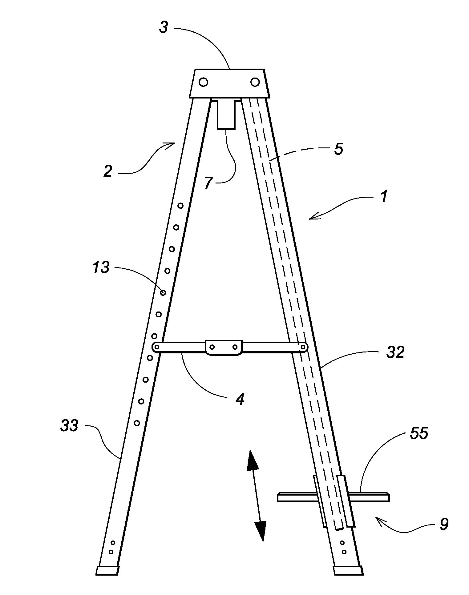
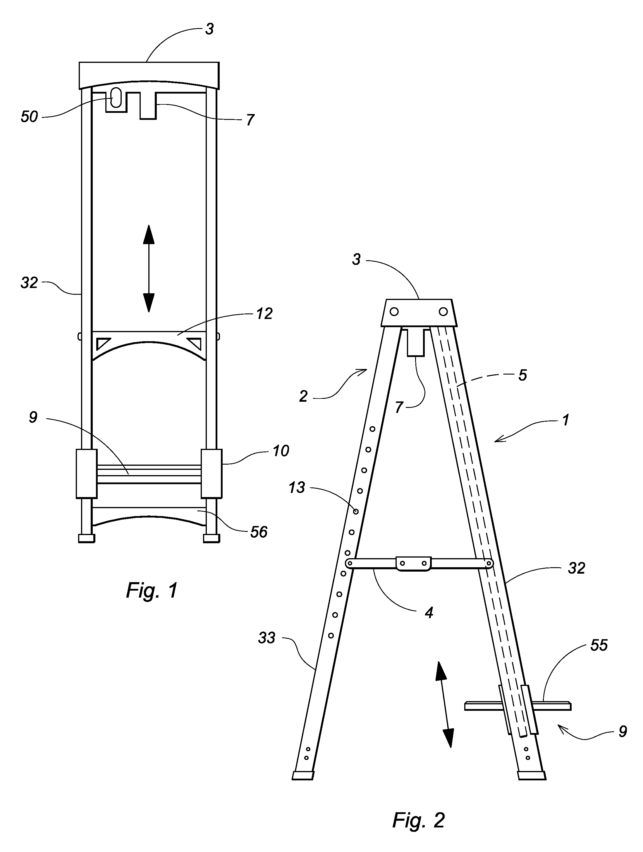
[0014]A stepladder comprises a front frame 1 and a rear frame 2 each formed of a pair of spaced side rails 32,33. A cover 3 is superimposed on the top ends of the frames while a pair of expandable brace members 4 extend between intermediate portions, similar to a conventional stepladder; as with many conventional stepladders, the cover includes recesses and apertures for receiving paint cans, tools, light bulbs and similar items; the brace members allow the frame members to expand to a substantially V-shaped configuration when the ladder is in use, or to contract to a substantially linear configuration for storage.

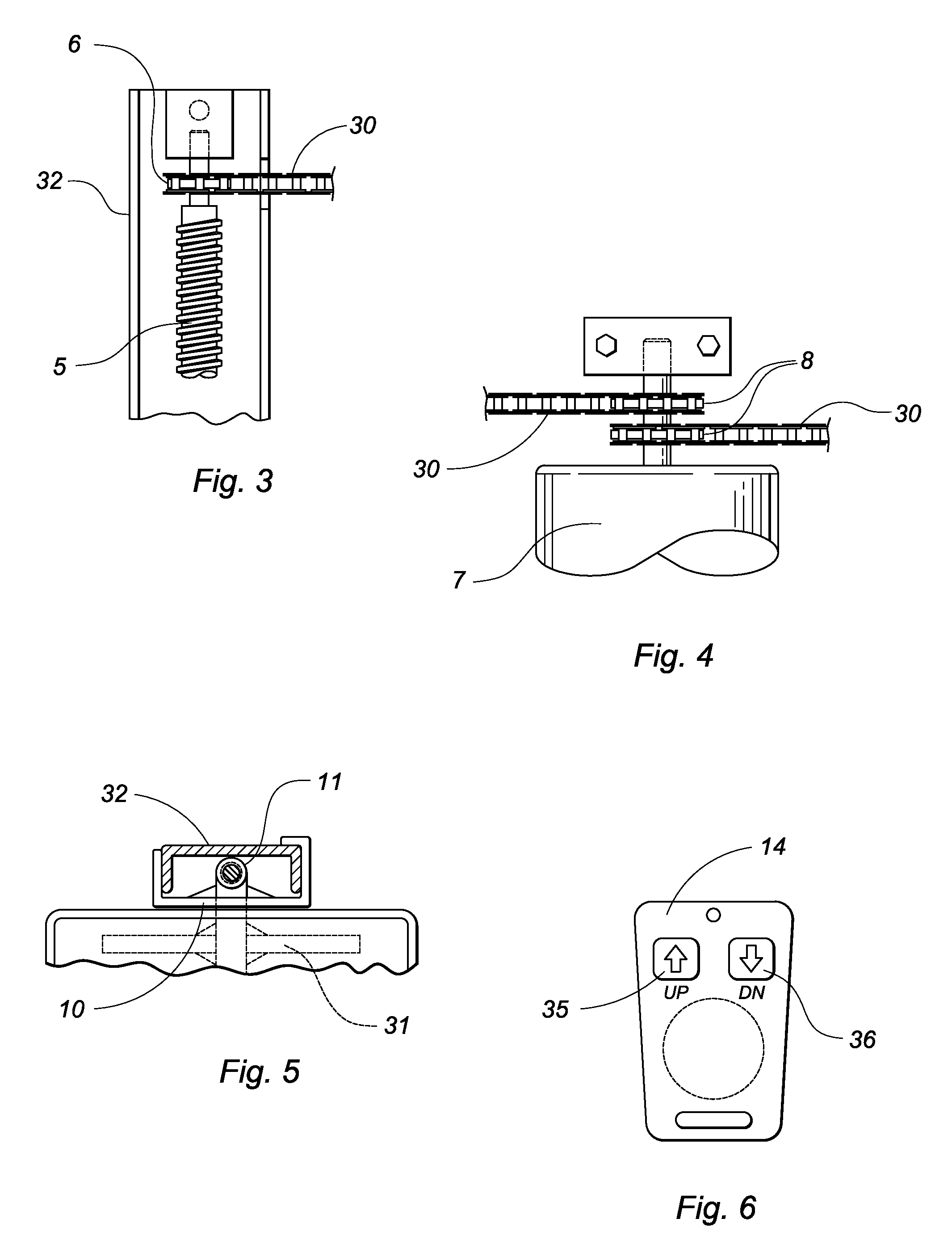
[0015]Axially received within each front frame member side rail 32 is an elongated drive screw 5 having a drive gear 6 at a top end thereof. Positioned within the cover 3 is a reversible motor 7 and an associated rechargeable battery 50; the motor drives a pair of sprockets 8 in either of two directions. A designated chain 30 encompasses one of the drive gears 6 and one of...


PUM


Abstract

A stepladder comprises a front frame and a rear frame each formed of a pair of spaced side rails. A motor-driven step is slidably mounted on the front frame side rails. The motor is controlled with a remote unit allowing a worker to automatically raise and lower the step when accessing an elevated area.

Description

CROSS REFERENCE TO RELATED APPLICATIONS[0001]This application is entitled to the benefit of provisional application No. 60 / 986,009 filed on Nov. 7, 2007, the specification of which is incorporated herein by reference.BACKGROUND OF THE INVENTION[0002]The present invention relates to a ladder having a motorized step that can be automatically raised and lowered.DESCRIPTION OF THE PRIOR ART[0003]A stepladder includes multiple, tiered rungs that a worker sequentially climbs when accessing an elevated area. Usually, the worker must repeatedly ascend and descend the ladder, which is laborious and inconvenient. Furthermore, balancing on the narrow rungs while climbing the ladder or standing is tedious and unsafe. Accordingly, there is currently a need for a stepladder that is safer and easier to ascend and descend than conventional stepladders. The present invention addresses this need by providing a stepladder having a motorized step on which a worker stands that can be automatically raise...

Claims


Application Information

Patent Timeline
IPC IPC(8): E06C7/16
CPCE06C1/16E06C7/16
Inventor GREGERSEN, CHARLES
Owner BRANDON J BOWER
Why Eureka
Try Eureka