Team trekking device and methods of using same

a technology of trekking device and foot, which is applied in the field of recreation apparatus, can solve the problems of unrecognized and unsatisfactory needs to make the device safer and easier to use, prone to twisting of the rubber of the inner tube, and the inner tube wrapping around the bottom of the tube, so as to minimize the twisting of the foot and facilitate us

Inactive Publication Date: 2007-10-30
STEBLER JR PHILIP F
View PDF10 Cites 6 Cited by
  • Summary
  • Abstract
  • Description
  • Claims
  • Application Information

AI Technical Summary

Benefits of technology

[0007]The present invention improves upon the prior art team trekking devices. The improvements make the device embodiments of the present invention safer and easier to use than those of the prior art. In such embodiments, the team trekking devices comprise individual lengths of a durable material, each individual length having attached to it a plurality of foot securing devices spaced along its top surface. Each of the plurality of foot securing devices is constructed so as to maintain the alignment of the user's foot with the length of durable material to which it is attached and thus minimize twisting of the foot relative to the length of durable material. Each such trekking device is hereinafter identified by the word “trekker.” A set of two trekkers is hereinafter identified as a “pair of trekkers.”
[0011]In some method embodiments of the present invention involving the use of three or more trekkers, the trekkers are laid out in an array wherein three or more individual trekkers are aligned parallel to one another. Individuals mount the trekkers so that at least one individual is astride each set of adjacent trekkers and together the individuals of the group effectively interconnect all of the trekkers into an array that moves as a segmented unit as the group achieves group locomotion.

Problems solved by technology

Although such prior art team trekking devices have been used for decades, the need to make the devices safer and easier to use has gone unrecognized and unsatisfied.
However, that device had several drawbacks.
One such drawback was that the inner tube wrapping around the bottom would tear after a relatively short period of use and was also prone to marking hard surfaces traversed.
Another drawback was that the rubber of inner tubes tended to twist when the piece of lumber to which it was attached was turned or when one person fell out of coordination with the group as to the direction and / or timing of his or her motions.
This compromised the controllability of the team trekking device and tended to cause the users to fall, giving rise to the danger twisted ankles and other injuries.

Method used


Image

  • Team trekking device and methods of using same
  • Team trekking device and methods of using same
  • Team trekking device and methods of using same

Examples


Embodiment Construction

[0030]In this section, some preferred embodiments of the present invention are described in detail sufficient for one skilled in the art to practice the present invention. It is to be understood, however, that the fact that a limited number of preferred embodiments are described herein does not in any way limit the scope of the present invention as set forth in the appended claims.

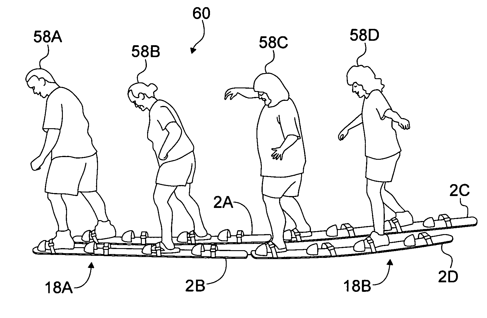
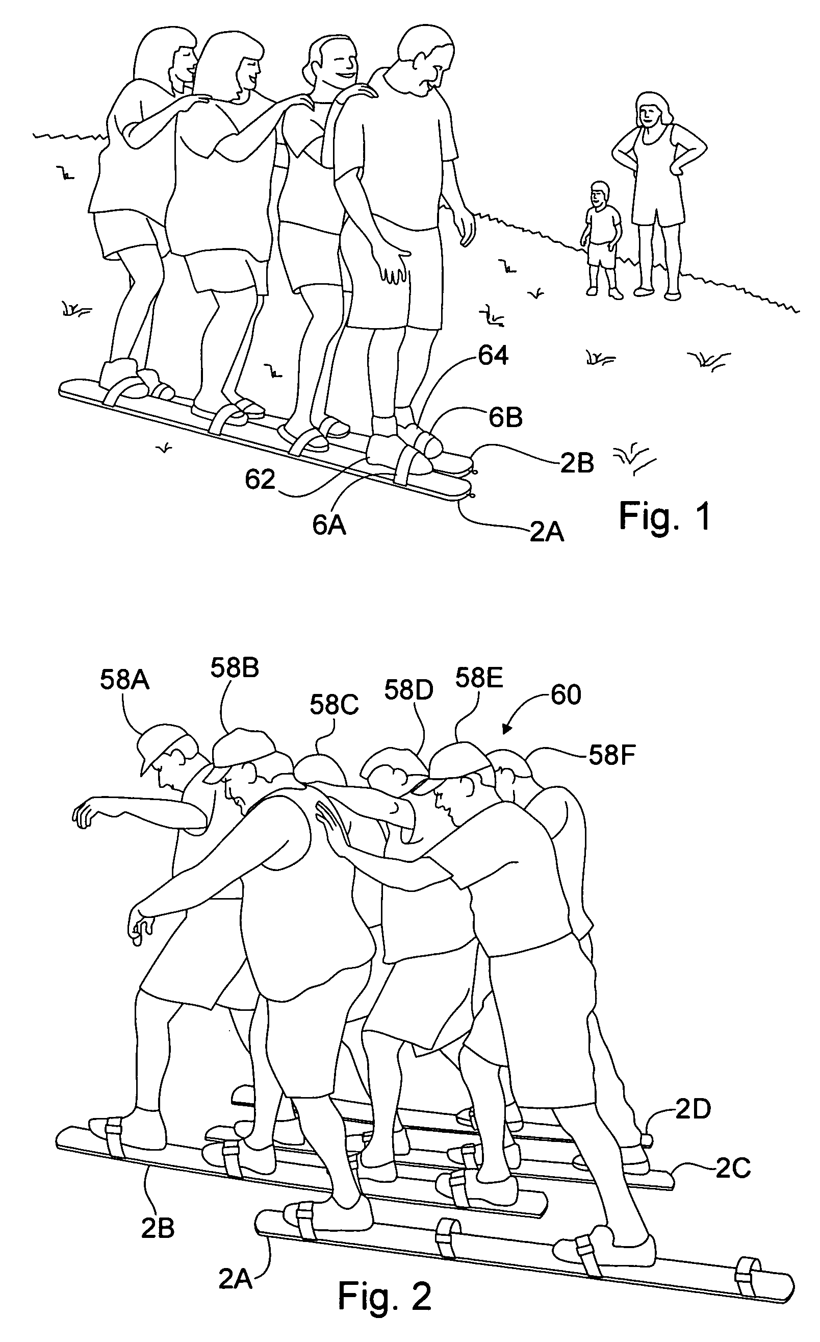
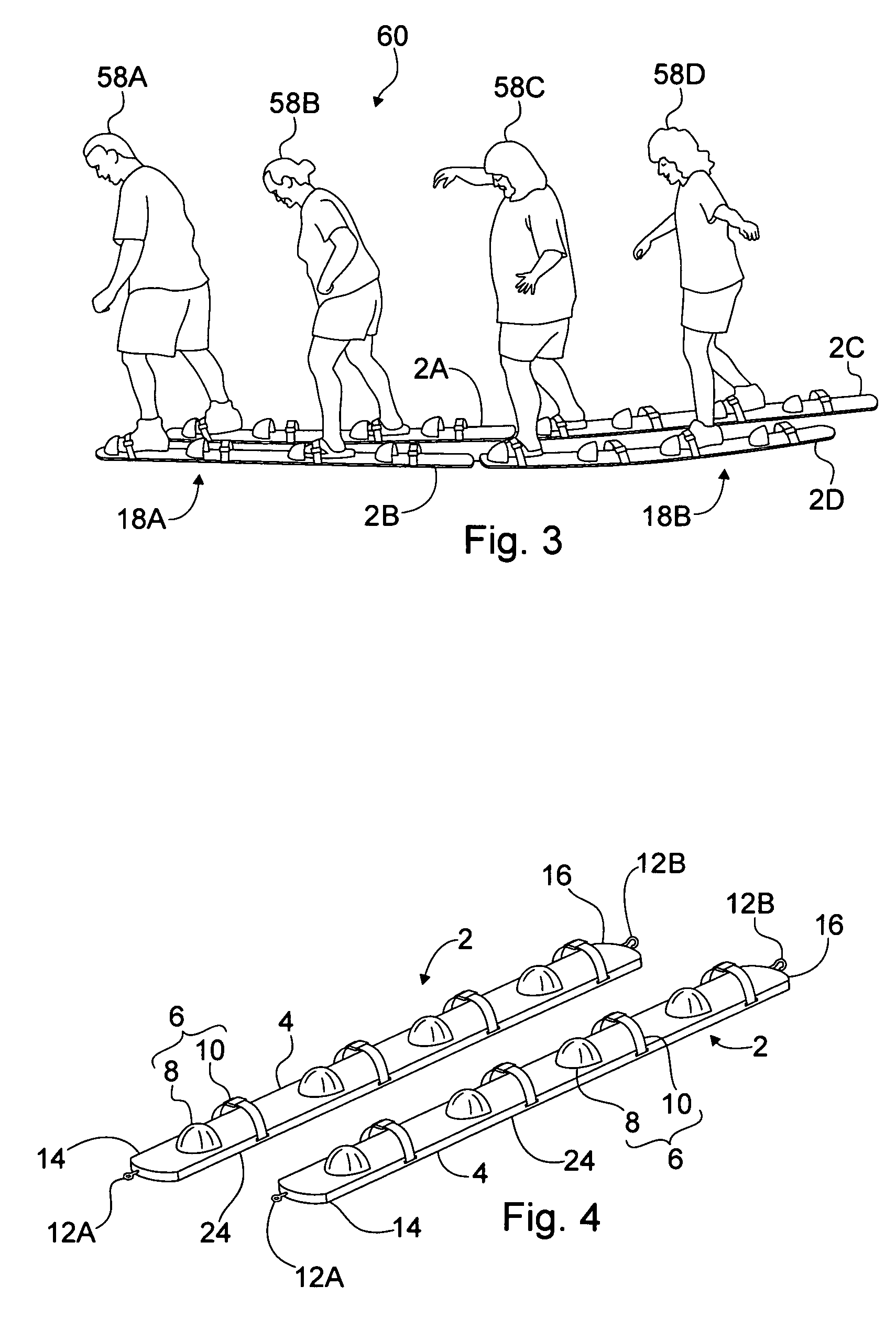
[0031]FIGS. 1-3 illustrate one or more pairs of trekkers according to the present invention in use by groups of individuals. FIG. 4 shows a preferred embodiment of a pair of trekkers according to the present invention. Referring to FIG. 4, each trekker 2 of the shown embodiment comprises a plank-like base member 4 and a plurality of foot securing devices 6. The base member 4 is preferably wider than the foot width of the intended users. More preferably, the width of the base member 4 is about five inches. Preferably, the thickness of the base member 4 is substantially less than the width of the base member...


PUM


Abstract

Trekkers for group use are disclosed. Each trekker has a plurality of foot securing devices and may have connectors at its ends for connecting the trekker in tandem with another trekker. Methods of using the trekkers are also disclosed. The methods include ways of using the trekkers in tandem and in arrays.

Description

BACKGROUND OF THE INVENTION[0001]1. Field of the Invention[0002]The present invention relates to recreational apparatuses that are jointly used by a plurality of individuals. More particularly, the present invention relates to trekking devices that are jointly operated by a team of two or more individuals. The present invention also relates to methods of using team trekking devices.[0003]2. Description of the Related Art[0004]Team sports are enjoyed worldwide. They are invigorating, foster a sense of community and common purpose, and include an element of coordinated group action. They may be engaged in for recreation, for exercise, or as a means of developing a team spirit among a group of individuals.[0005]Among such sports are those which require coordinated group locomotion. One such sport involves a group of individuals who stand astride the tops of two parallel pieces of lumber. Each individual holds onto two ropes that are attached to the lumber pieces. One of the ropes is at...

Claims


Application Information

Patent Timeline
Patent Type & Authority Patents(United States)
IPC IPC(8): A63B22/00
CPCA63B21/143A63B21/285A63B23/0405A63B26/00A63B67/00A63B25/00A63B2069/0062A63B21/4015A63B69/0062
Inventor STEBLER, JR., PHILIP F.
Owner STEBLER JR PHILIP F
Why Eureka
Try Eureka