
Aerial work platform apparatus and method

Inactive Publication Date: 2013-08-13
BOGUE MARC
View PDF31 Cites 32 Cited by
  • Summary
  • Abstract
  • Description
  • Claims
  • Application Information

AI Technical Summary

Benefits of technology

The present invention is a new aerial work platform that is safer and easier to use than existing lifts. It allows the user to automatically level the platform, which saves time and encourages operators to ensure safety before use. The technical effect of the invention is to provide a better and more convenient solution for supporting and leveling aerial work platforms.

Problems solved by technology

While the devices known in the art offer various solutions to the broad issue of supporting and leveling an aerial work platform, no known device exists which allows a user to automatically level an aerial work platform, both encouraging operators to ensure that the lift is level before use and expediting the time needed to prepare the platform for use.

Method used


Image

  • Aerial work platform apparatus and method
  • Aerial work platform apparatus and method
  • Aerial work platform apparatus and method

Examples


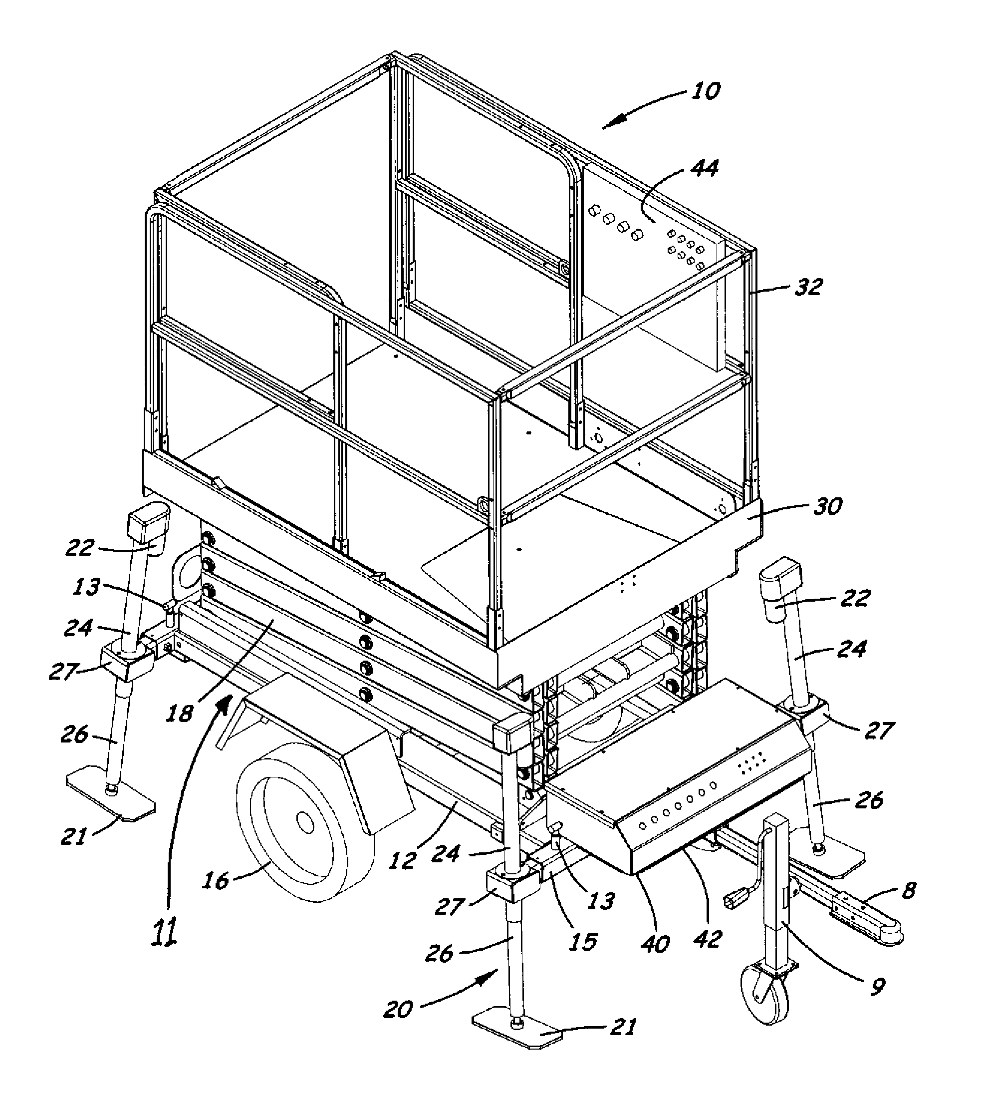
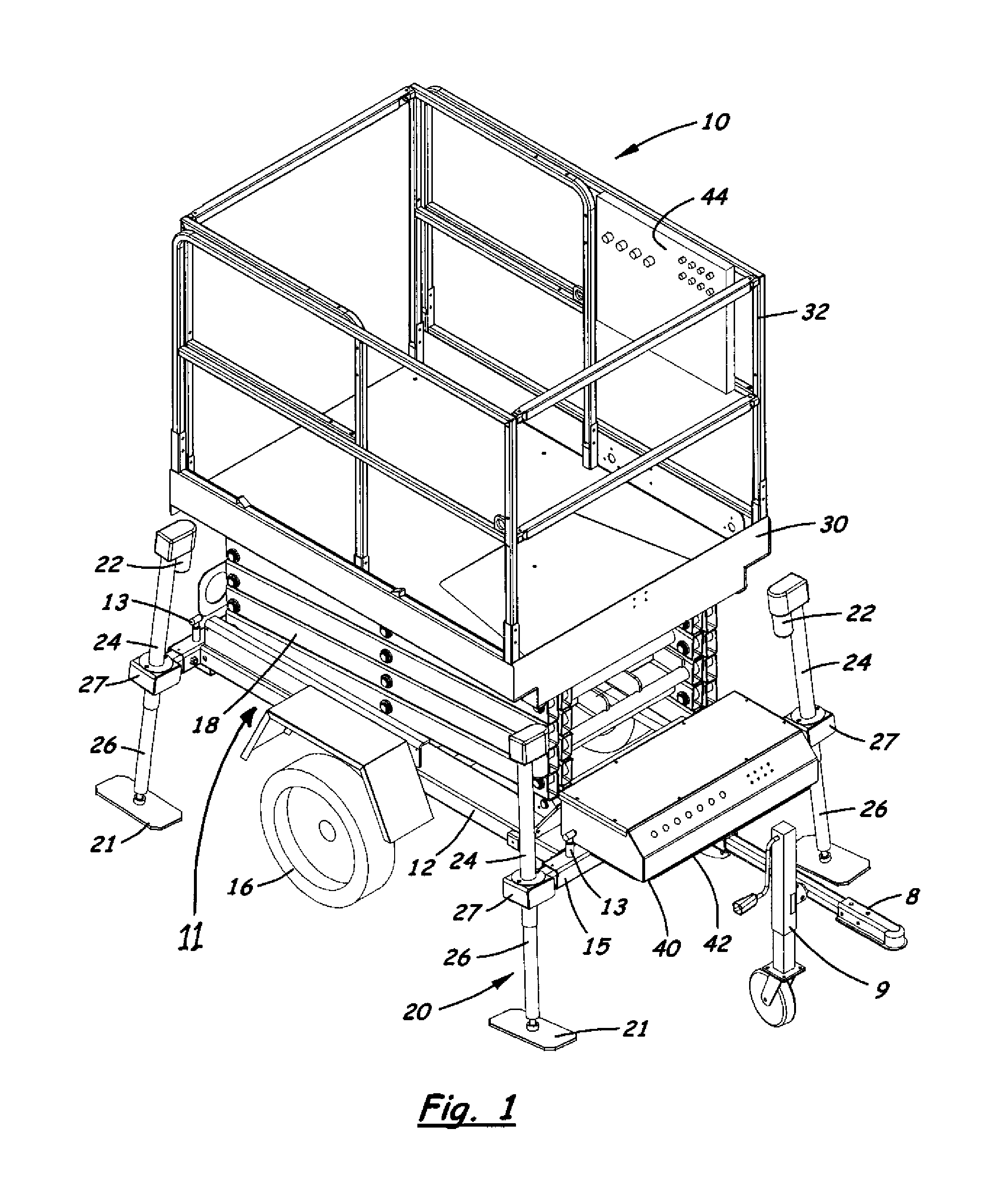
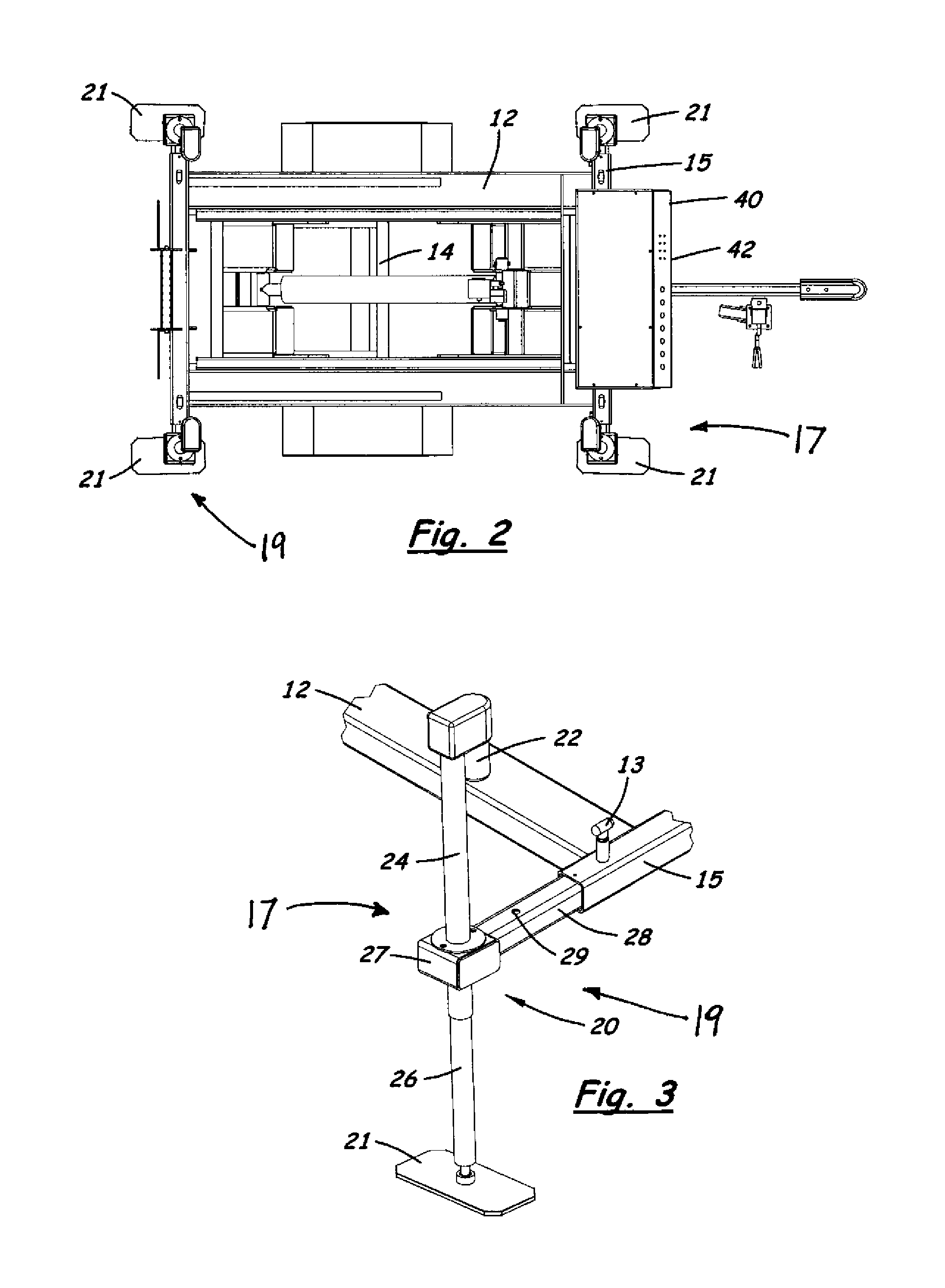
Embodiment Construction

[0028]With reference now to the drawings, and in particular to FIGS. 1 through 10 thereof, a new aerial work platform apparatus and method embodying the principles and concepts of the present invention will be described.

[0029]In FIGS. 1 and 2, elements of the aerial work platform apparatus 10 are shown in their generally retracted position which is suitable for transport or travel of the apparatus between sites, such as movement along a road or highway. In FIGS. 3 and 4, the elements of the apparatus 10 are shown in a generally extended position suitable for use such as raising the platform above the ground surface. The aerial work platform apparatus 10 may be used for providing safe, temporary access to elevated areas. The aerial work platform apparatus 10 may include an automatic leveling feature to help reduce the risk of the apparatus overturning when the platform is raised or elevated, as compared to an elevated platform apparatus which has not been put in a sufficiently level ...


PUM


Abstract

An aerial work platform apparatus and method for automatically leveling a mobile aerial work platform, including a base frame, a movable platform, a lift mechanism configured to move the platform in a substantially vertical direction with respect to the base frame, a stabilizing assembly including at least one outrigger leg mounted on the base frame, and a control assembly.

Description

BACKGROUND OF THE INVENTION[0001]1. Field of the Invention[0002]The present invention relates to aerial work platforms, and more particularly pertains to a new aerial work platform apparatus and method that are safer and easier to use that foregoing lifts.[0003]2. Description of the Prior Art[0004]Aerial work platforms (AWPs) encompass a variety of different configurations, all designed for the purpose of providing temporary access to elevated areas. Numerous types of lifting mechanisms may be employed for raising and lowering AWPs, including articulated lifts, such as bucket trucks, boom lifts or “cherry pickers,” scissor lifts, and mechanical lifts, such as those employing rack and pinion elements or screw thread elements. Scissor lifts, in contrast to boom lifts, are able to move in only in a vertical direction, because of the scissor mechanism. The scissor mechanism comprises a support with a plurality of pivotally linked, folding elements that criss-cross each other in a substa...

Claims


Application Information

Patent Timeline
IPC IPC(8): C05B11/00
CPCB66F11/042
Inventor BOGUE, MARC
Owner BOGUE MARC
Learn More