AI technical title is built by PatSnap AI team. It summarizes the technical point description of the patent document.
a polymer coating and inkjet printer technology, applied in printing and other directions, can solve the problems of unwanted microscopic fissures that are typically inevitable, and achieve the effects of improving durability, scratch resistance, and wettability
Active Publication Date: 2011-09-06
MEMJET TECH LTD +1
View PDF4 Cites 0 Cited by
Summary
Abstract
Description
Claims
Application Information
AI Technical Summary
This helps you quickly interpret patents by identifying the three key elements:
Problems solved by technology
Method used
Benefits of technology
Benefits of technology
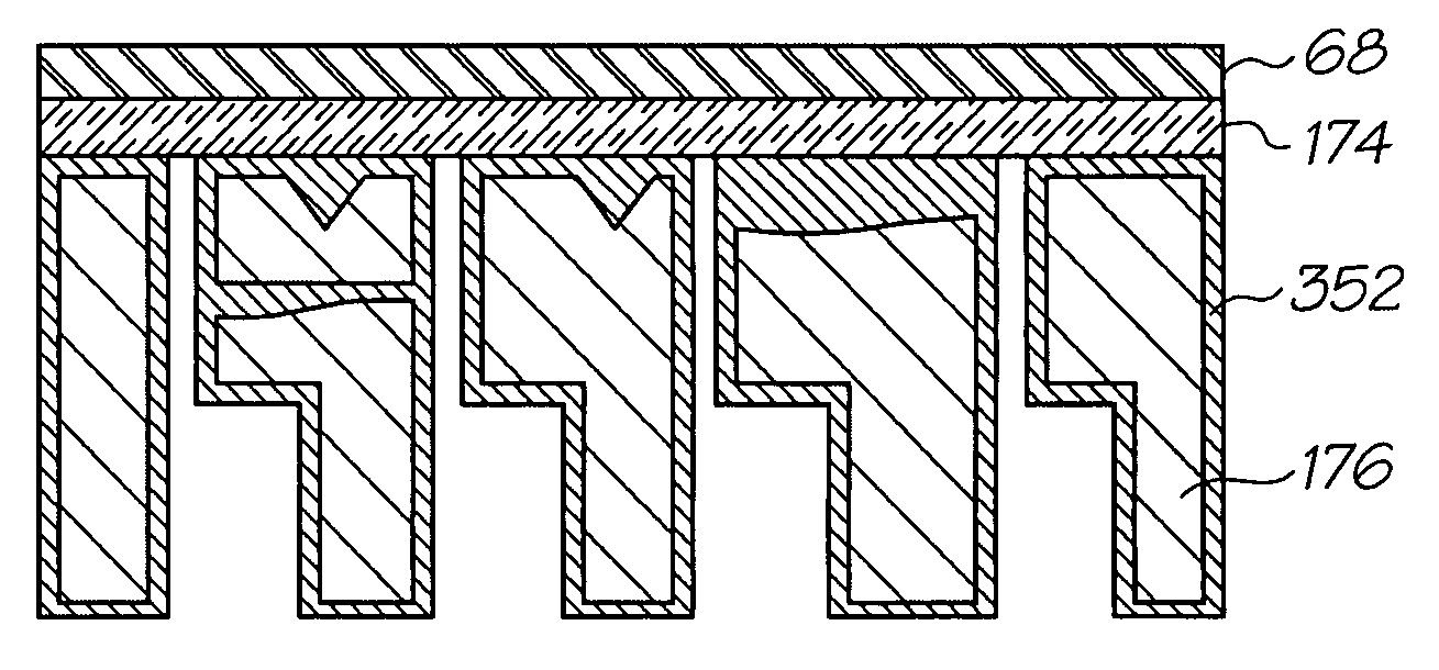
The present invention provides a printhead assembly and a method of fabricating the assembly that minimizes ink leakages by plugging microscopic fissures in the molded ink manifold with a polymercoating. The polymer coating is applied to the molded ink manifold by dipping, spray coating or spin coating. The printhead integrated circuits are then bonded to the coated manifold bonding surface or an adhesive film. The technical effect of this invention is to minimize ink leakages and improve the reliability of the printhead assembly.
Problems solved by technology
Some unwanted microscopic fissures are typically inevitable, even when using high tolerance molding tools.
Method used
Image
Click on the blue label to locate the original text in one second.
Reading with bidirectional positioning of images and text.
Examples
Embodiment Construction
Overview
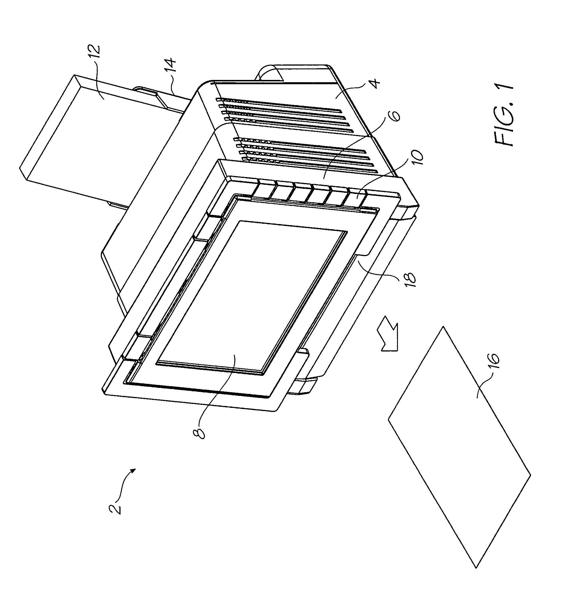
[0084]FIG. 1 shows a printer 2 embodying the present invention. The main body 4 of the printer supports a media feed tray 14 at the back and a pivoting face 6 at the front. FIG. 1 shows the pivoting face 6 closed such that the display screen 8 is its upright viewing position. Control buttons 10 extend from the sides of the screen 8 for convenient operator input while viewing the screen. To print, a single sheet is drawn from the media stack 12 in the feed tray 14 and fed past the printhead (concealed within the printer). The printed sheet 16 is delivered through the printed media outlet slot 18.
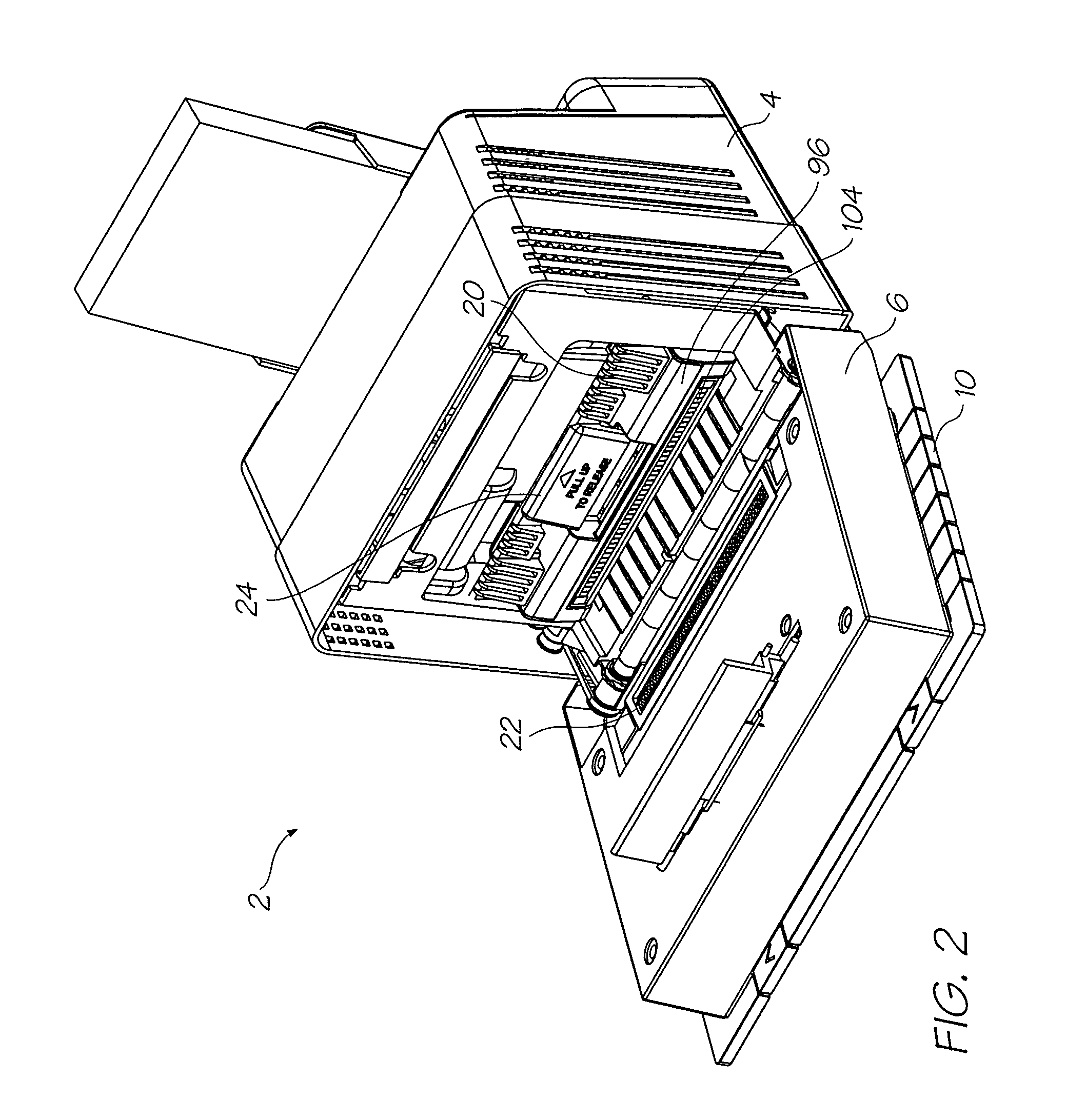
[0085]FIG. 2 shows the pivoting front face 6 open to reveal the interior of the printer 2. Opening the front face of the printer exposes the printhead cartridge 96 installed within. The printhead cartridge 96 is secured in position by the cartridge engagement cams 20 that push it down to ensure that the ink coupling (described later) is fully engaged and the printhead ICs (described l...
PUM
Abstract
A printhead assembly includes a molded ink manifold, a plurality of printhead integrated circuits, and an adhesive film sandwiched between the ink manifold and the printhead integrated circuits. A manifold bonding surface of the molded ink manifold includes a polymercoating. The polymercoating plugs fissures resulting from a molding process used to mold the ink manifold.
Description
FIELD OF THE INVENTION[0001]The present invention relates to printers and in particular inkjet printers.CO-PENDING APPLICATIONS[0002]The following application has been filed by the Applicant simultaneously with the present application:[0003]Ser. No. 12 / 334,520[0004]The disclosure of this co-pending application is incorporated herein by reference. The above application has been identified by its filing docket number, which will be substituted with the corresponding application number, once assigned.CROSS REFERENCES[0005]The following patents or patent applications filed by the applicant or assignee of the present invention are hereby incorporated by cross-reference.[0006]7,344,2267,328,97611 / 685,08411 / 685,08611 / 685,09011 / 740,92511 / 763,44411 / 763,44311 / 946,8407,441,87912 / 017,77112 / 205,90812 / 264,90312 / 265,63712 / 323,47112 / 323,47212 / 323,47311 / 607,9767,416,2807,278,7176,755,5097,347,5376,692,1087,407,2716,672,7097,303,2637,086,7187,429,0976,672,71010 / 534,8126,669,3347,322,6867,152,9587,281...
Claims
Application Information
Patent Timeline
Application Date:The date an application was filed.
Publication Date:The date a patent or application was officially published.
First Publication Date:The earliest publication date of a patent with the same application number.
Issue Date:Publication date of the patent grant document.
PCT Entry Date:The Entry date of PCT National Phase.
Estimated Expiry Date:The statutory expiry date of a patent right according to the Patent Law, and it is the longest term of protection that the patent right can achieve without the termination of the patent right due to other reasons(Term extension factor has been taken into account ).
Invalid Date:Actual expiry date is based on effective date or publication date of legal transaction data of invalid patent.

