
Inkjet printhead with join regions seamlessly compensated by directional nozzles

a technology of directional nozzles and printheads, applied in the field of printers, can solve the problems of dead nozzle compensation, and increase the size of the print zon

Active Publication Date: 2014-05-06
MEMJET TECH LTD
View PDF14 Cites 0 Cited by
  • Summary
  • Abstract
  • Description
  • Claims
  • Application Information

AI Technical Summary

Benefits of technology

The patent text describes a way to make inkjet printers more effective and prevent ink from leaking during printing. This is done by coating the roof of the ink chamber with a special material that forms a tight seal between the paddles and the roof, reducing the likelihood of ink leakage. The material can also have openings that allow for a fluidic seal between the paddles and the roof. This results in a better inkjet printing process.

Problems solved by technology

Each technology may have its own advantages and disadvantages in the areas of cost, speed, quality, reliability, power usage, simplicity of construction operation, durability and consumables.
Stationary pagewith printheads, which extend across a width of a page, present a number of unique design challenges when compared with more conventional traversing inkjet printheads.
Other approaches to pagewidth printing (e.g. HP Edgeline™ Technology) employ staggered printhead modules, which inevitably increase the size of the print zone and place additional demands on media feed mechanisms in order to maintain proper alignment with the print zone.
Dead nozzle compensation is a particular problem in stationary pagewidth printheads, in contrast with traversing printheads, because the media substrate only makes a single pass of each nozzle in the printhead during printing.

Method used


Image

  • Inkjet printhead with join regions seamlessly compensated by directional nozzles
  • Inkjet printhead with join regions seamlessly compensated by directional nozzles
  • Inkjet printhead with join regions seamlessly compensated by directional nozzles

Examples


Embodiment Construction

Fabrication Process for Inkjet Nozzle Assembly Comprising Moveable Roof Paddle

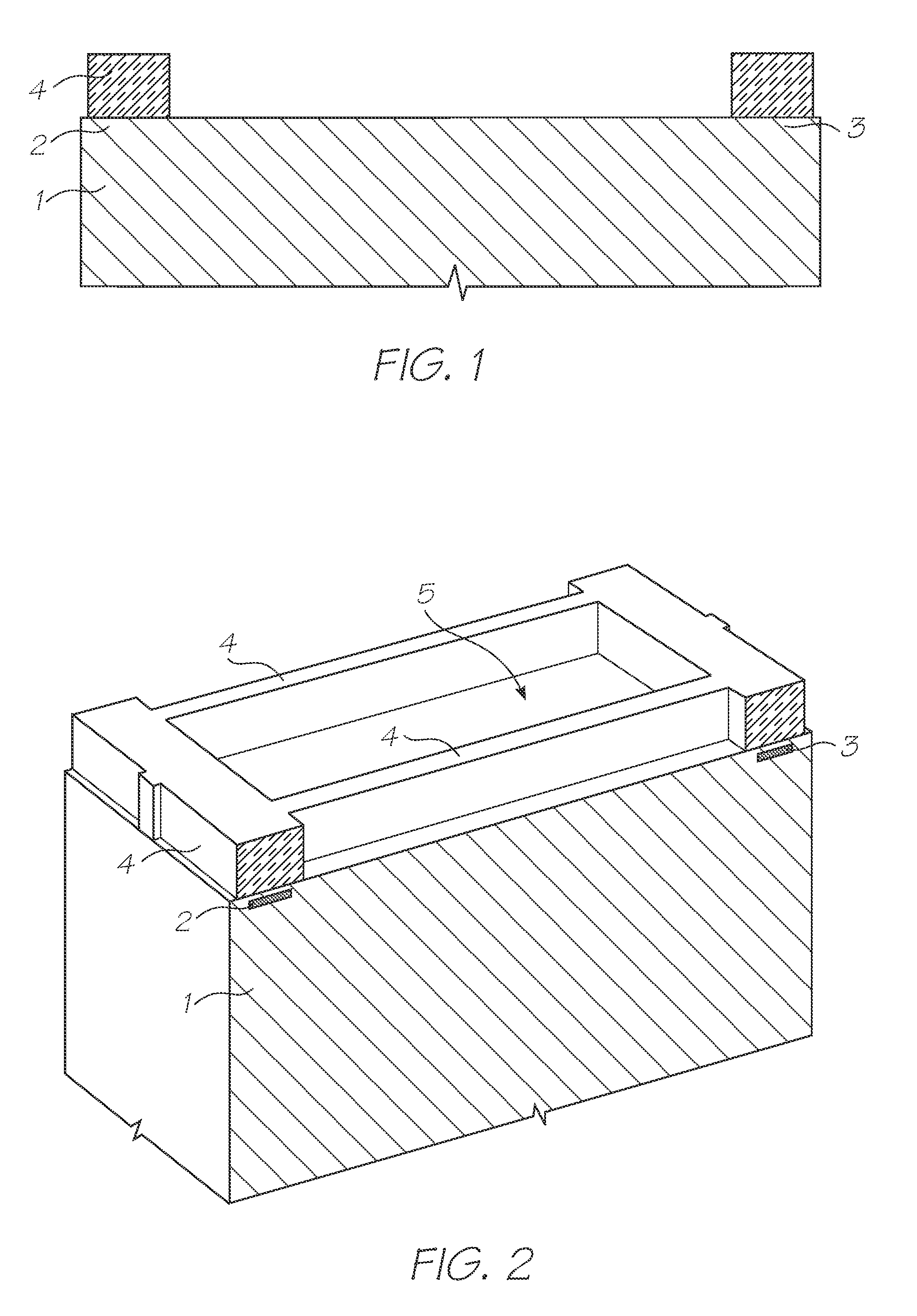
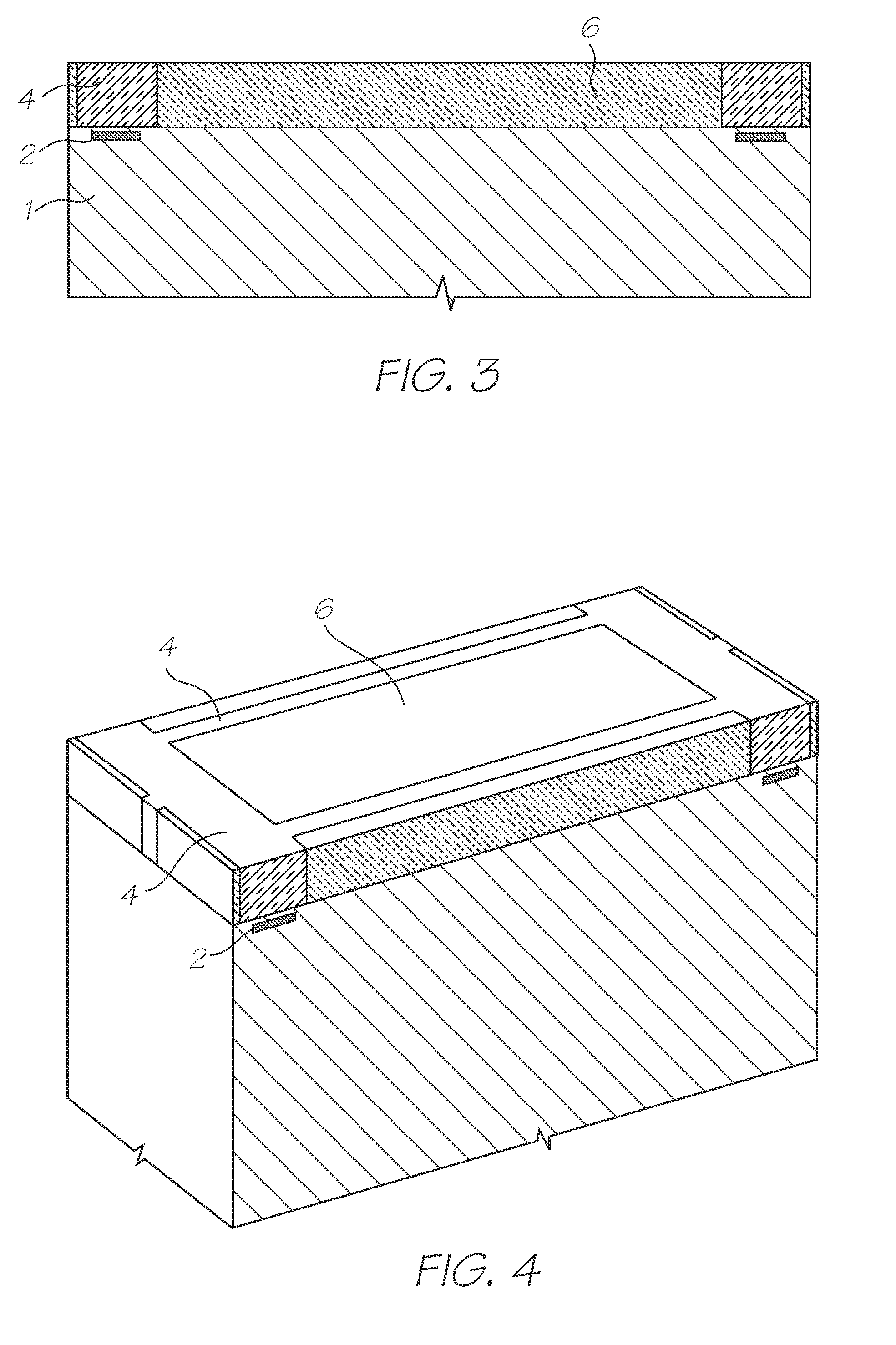
[0222]For the sake of completeness and by way of background, there will now be described a process for fabricating an inkjet nozzle assembly (or “nozzle”) comprising a moveable roof paddle having a thermal bend actuator. The completed inkjet nozzle assembly 100 shown in FIGS. 15 and 16 utilizes thermal bend actuation, whereby a movable paddle 4 in a nozzle chamber roof bends towards a substrate 1 resulting in ink ejection. This fabrication process was described in the Applicant's earlier US Publication No. US 2008 / 0309728 and US 2008 / 0225077, the contents of which are herein incorporated by reference. However, it will be appreciated that corresponding fabrication processes may be used to fabricate any of the inkjet nozzle assemblies, and indeed printheads and printhead integrated circuits (ICs), described herein.

[0223]The starting point for MEMS fabrication is a standard CMOS wafer having CMOS drive circui...


PUM


Abstract

A stationary pagewidth inkjet printhead has one or more nozzle rows extending along a longitudinal axis of the printhead. The printhead is comprised of a plurality of printhead modules having first and second opposite ends butted across a width of a page. Each butting pair of printhead modules defines a common join region, wherein a nozzle pitch across the join region exceeds one nozzle pitch, one nozzle pitch being defined as a minimum longitudinal distance between a pair of nozzles in a same nozzle row. A first nozzle positioned at the first end of a first printhead module in a butting pair is configured to fire ink droplets into a respective join region.

Description

FIELD OF THE INVENTION[0001]The present invention relates to the field of printers and particularly inkjet printheads. It has been developed primarily to improve print quality and printhead performance in high resolution printheads.COPENDING APPLICATIONS[0002]The following applications have been filed by the Applicant simultaneously with the present application:[0003]12 / 895,85612 / 895,85712 / 895,85812 / 895,85912 / 895,86112 / 895,86212 / 895,86312 / 895,86412 / 895,86512 / 895,86612 / 895,867[0004]The disclosures of these co-pending applications are incorporated herein by reference.BACKGROUND OF THE INVENTION[0005]Many different types of printing have been invented, a large number of which are presently in use. The known forms of print have a variety of methods for marking the print media with a relevant marking media. Commonly used forms of printing include offset printing, laser printing and copying devices, dot matrix type impact printers, thermal paper printers, film recorders, thermal wax print...

Claims


Application Information

Patent Timeline
Patent Type & Authority Patents(United States)
IPC IPC(8): B41J2/205
CPCB41J2/14427
Inventor MCAVOY, GREGORY JOHNKERR, EMMA ROSEO'REILLY, RONAN PADRAIG SEANLAWLOR, VINCENT PATRICKBAGNAT, MISTY
Owner MEMJET TECH LTD
Learn More