
Unit-cell array optical signal processor

Inactive Publication Date: 2011-09-13
HRL LAB
View PDF16 Cites 34 Cited by
  • Summary
  • Abstract
  • Description
  • Claims
  • Application Information

AI Technical Summary

Problems solved by technology

When this perfect destructive interference occurs, all of the light is coupled into the resonator.

Method used


Image

  • Unit-cell array optical signal processor
  • Unit-cell array optical signal processor
  • Unit-cell array optical signal processor

Examples


Embodiment Construction

[0059]The apparatus and methods of the present invention will now be described in detail by reference to various non-limiting embodiments of the invention.

[0060]Unless otherwise indicated, all numbers expressing dimensions, frequencies, parameters, and so forth used in the specification and claims are to be understood as being modified in all instances by the term “about.” Without limiting the application of the doctrine of equivalents to the scope of the claims, each numerical parameter should at least be construed in light of the number of reported significant digits and by applying ordinary rounding techniques.

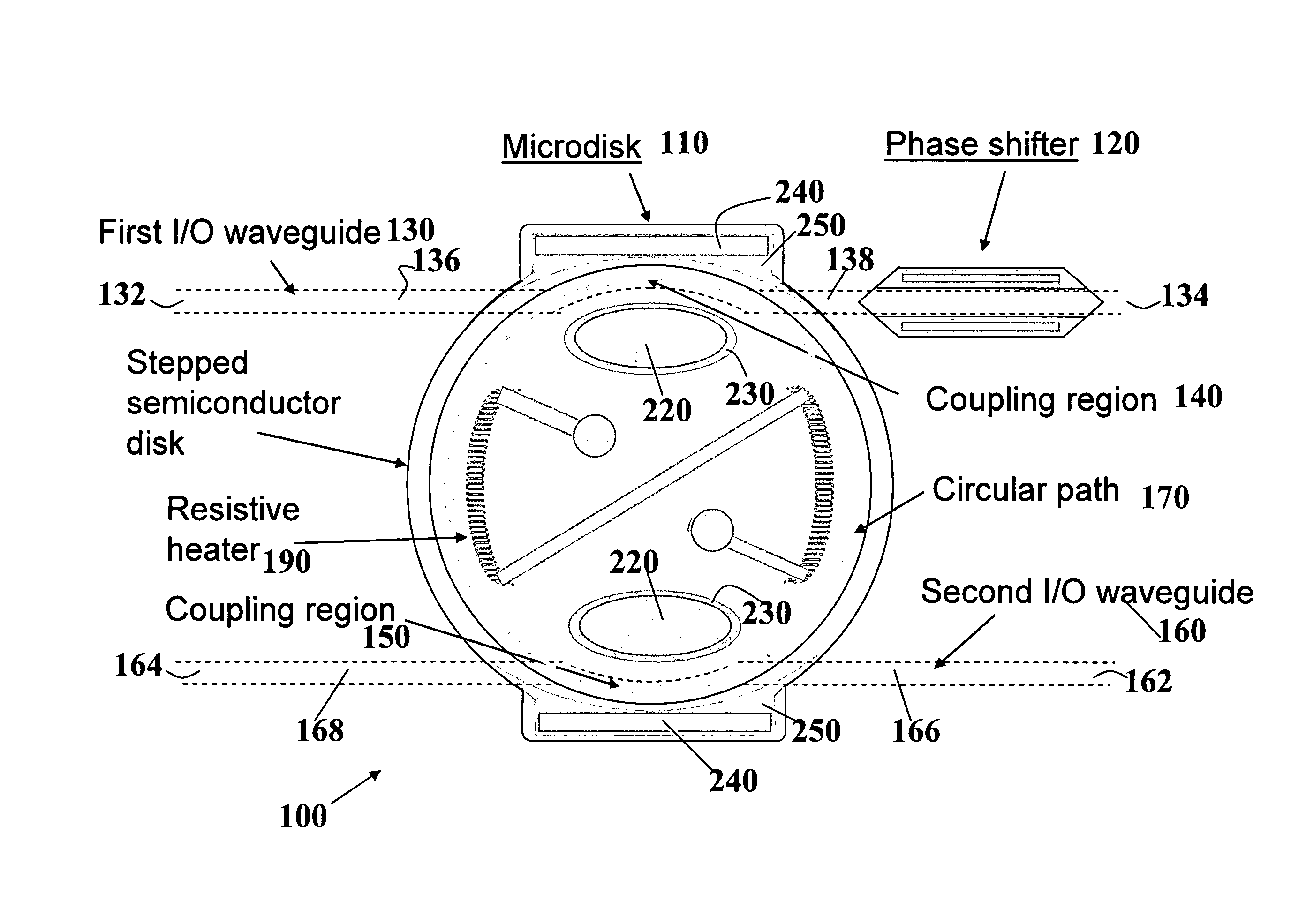
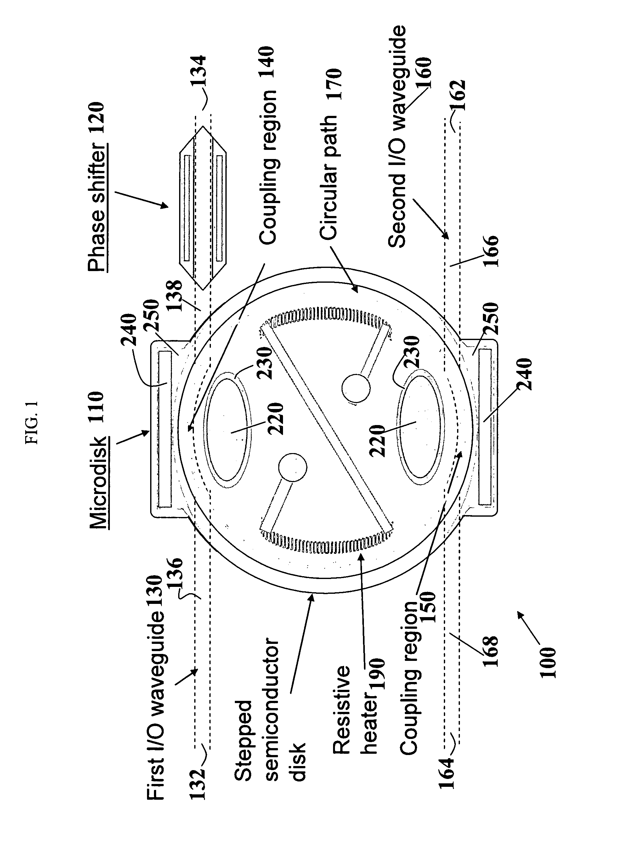
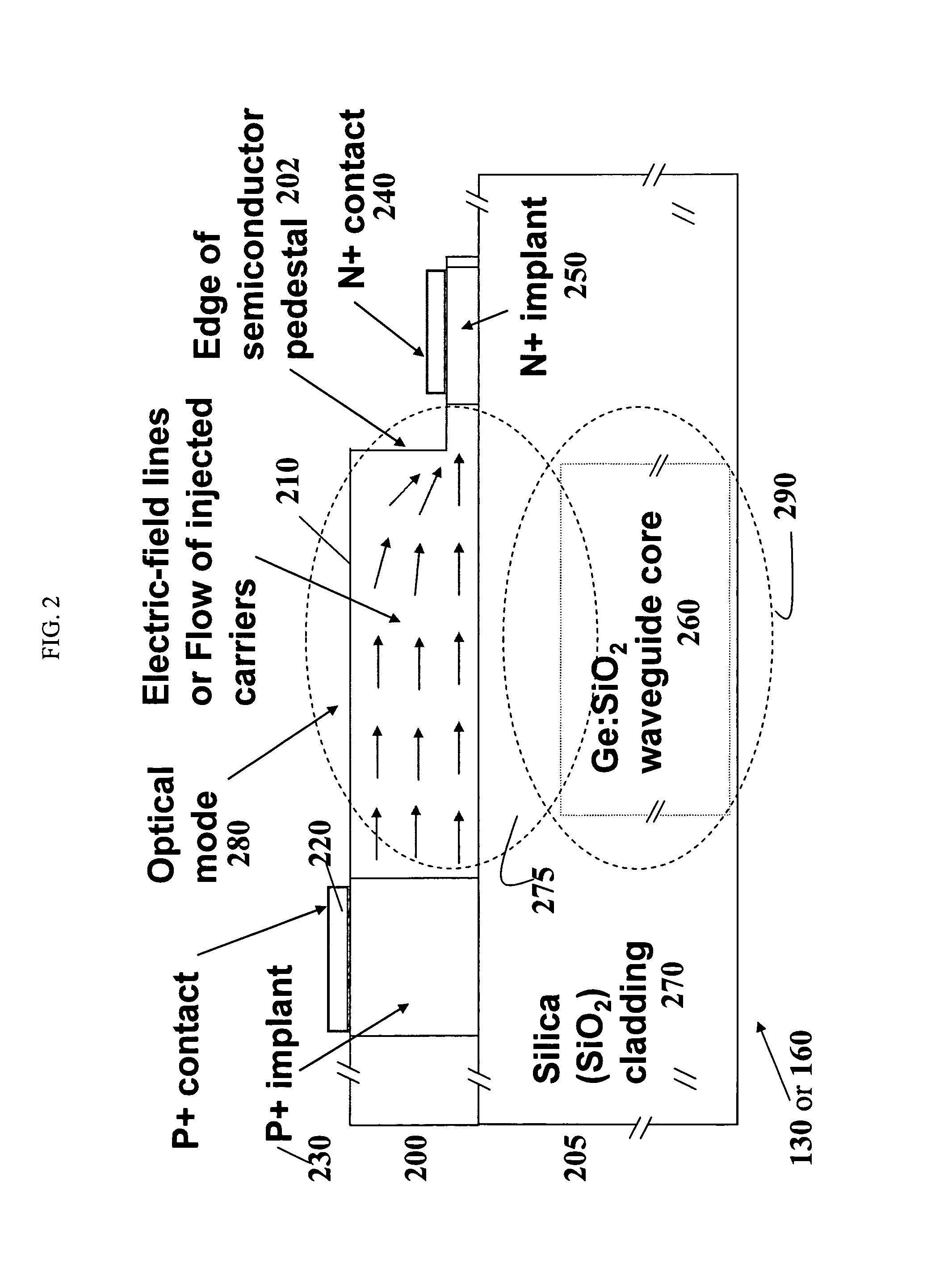
[0061]The disclosure herein describes, inter alia, an elemental unit cell from which to construct filter building blocks. As will be appreciated by a skilled artisan, the unit cell of the present invention can be a versatile component that is capable of performing the different functions of the various separate components contained in filter building blocks. In various embo...


PUM

PropertyMeasurementUnit
sizeaaaaaaaaaa
thicknessaaaaaaaaaa
refractive indexaaaaaaaaaa

Abstract

This invention provides a versatile unit cell as well as programmable and reconfigurable optical signal processors (such as optical-domain RF filters) that are constructed from arrays of those unit cells interconnected by optical waveguides. Each unit cell comprises an optical microdisk, an optical phase shifter, and at least one input / output optical waveguide, wherein the microdisk and the phase shifter are both optically connected to a common waveguide.

Description

RELATED APPLICATIONS[0001]Some embodiments of the present invention relate to embodiments and features described in U.S. patent application Ser. No. 61 / 028,625 (Ng et al.), filed Feb. 14, 2008, the disclosure of which is hereby incorporated by reference in its entirety, and which assignee is the same as the assignee of this patent.FIELD OF THE INVENTION[0002]The present invention generally relates to communication and signal-processing systems, and relates more specifically to methods and devices for optical signal processing.BACKGROUND OF THE INVENTION[0003]The ever-increasing demand for broadband communication systems has led to optical-transmission systems based on optical waveguides such as optical fibers and on optical processing elements for use in these systems. Generally, in high-performance communication systems, photons continue to supplant electrons as messengers.[0004]Significant effort has been spent towards optical integrated circuits having high complexity and advance...

Claims


Application Information

Patent Timeline
Patent Type & Authority Patents(United States)
IPC IPC(8): G02F1/035G02B6/26G02B6/42G02F1/01G02F1/295
CPCG02B6/12007G02B6/29395G02B6/29343G02B6/29383G02F2001/212G02F2203/15G02F2203/50G02F1/3132G02F1/212
Inventor YAP, DANIEL
Owner HRL LAB
Learn More