Check patentability & draft patents in minutes with Patsnap Eureka AI!

Electrical connector with improved contact arrangement

a technology of contact arrangement and electric connector, which is applied in the direction of electrical apparatus, electrical discharge tube, coupling device connection, etc., can solve the problems of insufficient transmission rate of usb, inability to meet the requirements of many electric devices, and difficulty in assembling a large number of signal pins

Active Publication Date: 2011-09-20
HON HAI PRECISION IND CO LTD
View PDF4 Cites 18 Cited by
  • Summary
  • Abstract
  • Description
  • Claims
  • Application Information

AI Technical Summary

Benefits of technology

The connector achieves enhanced signal transmission speed while maintaining a compact, user-friendly design, compatible with standard USB 2.0 plugs, and simplifies the assembly process, reducing costs.

Problems solved by technology

However, as the development of electric industry, even the USB 2.0 can not satisfy the requirement of many electric devices.
For example, under a circumstance transmitting an audio or video file, which is always up to hundreds MB, even to 1 or 2 GB, currently transmission rate of USB is not sufficient.
However, these non-USB protocols, such as PCI Express which is useful for its higher possible data rates, a 26-pin connectors and wider card-like form factor limit the use of Express Cards, and SATA which uses two connectors, one 7-pin connector for signals and another 15-pin connector for power, are not used as broadly as USB protocols.
One important reason is that these non-USB connectors contain a greater number of signal pins than an existing USB connector and are physically larger as well, and the greater number of signal pins is assembled difficultly, especially in an electrical connector.
Due to its clumsiness, the PCI Express and SATA connector can not adapt to the development trend of gently, thin, short and small size.

Method used


Image

  • Electrical connector with improved contact arrangement
  • Electrical connector with improved contact arrangement
  • Electrical connector with improved contact arrangement

Examples


Embodiment Construction

[0021]In the following description, numerous specific details are set forth to provide a thorough understanding of the present invention. However, it will be obvious to those skilled in the art that the present invention may be practiced without such specific details. In other instances, well-known circuits have been shown in block diagram form in order not to obscure the present invention in unnecessary detail. For the most part, details concerning timing considerations and the like have been omitted inasmuch as such details are not necessary to obtain a complete understanding of the present invention and are within the skills of persons of ordinary skill in the relevant art.

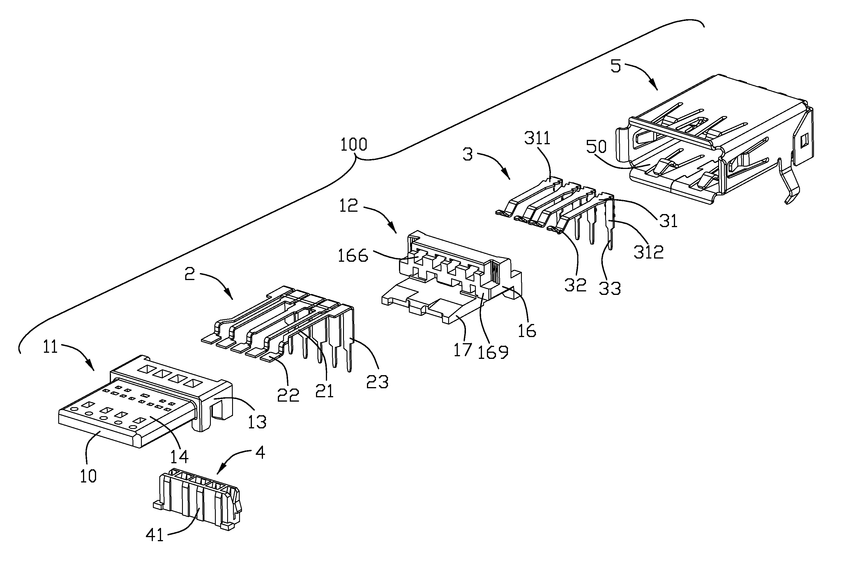
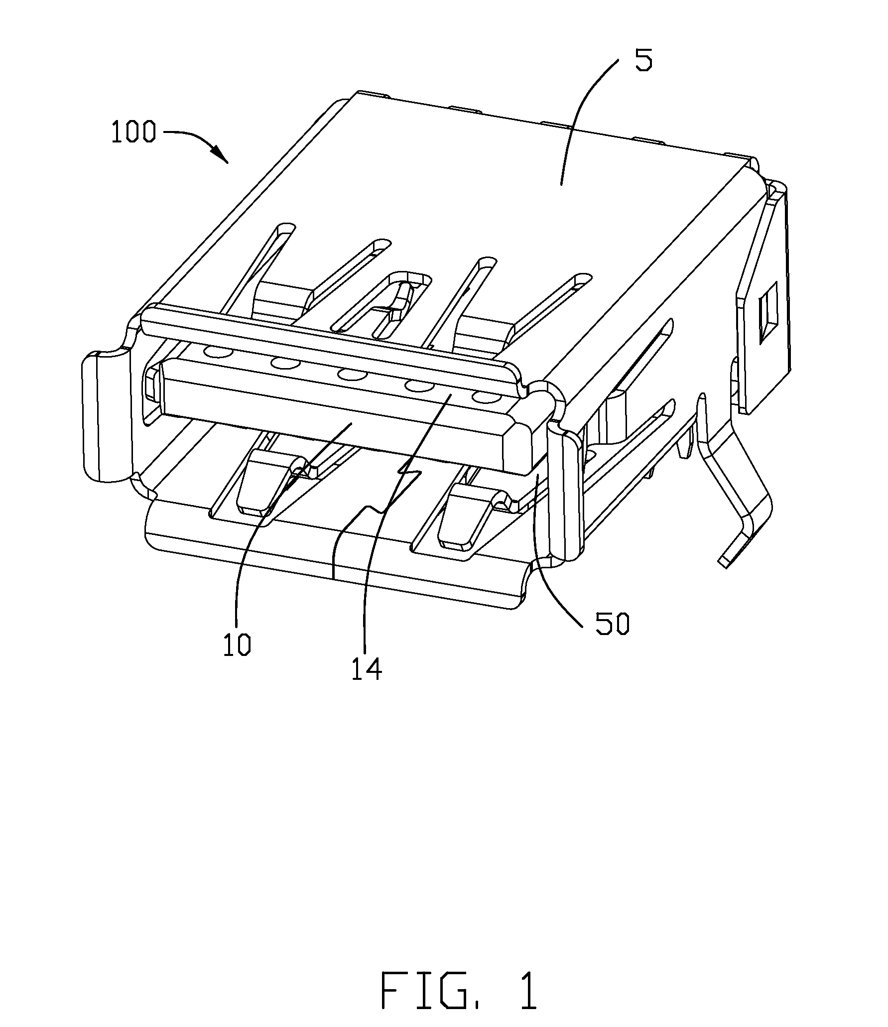
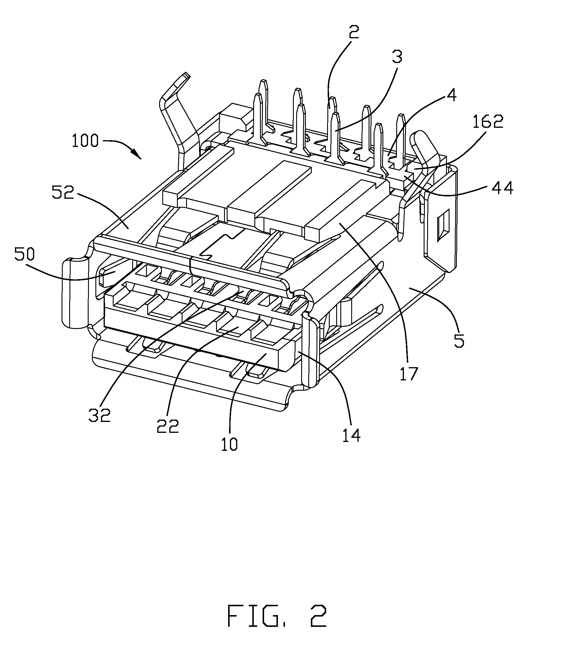
[0022]Referring to FIGS. 1-7, an electrical connector 100 according to the present invention is disclosed. The electrical connector 100 defines a mating face 10 and an insert opening 50 extending inwardly from the mating face 10. The electrical connector 100 comprises an insulative housing 1, a plurality of fir...


PUM


Abstract

An electrical connector (100) includes an insulative housing (10) which includes a first housing (11) and a second housing (12) engaging with each other, a number of first contacts (2) insert molded in the first housing (11), and a number of second contacts (3) retained in the second housing (12). The first housing (11) has a body portion (13) and a tongue (14) extending from the body portion (13). Each first contact (2) has a first contact portion (22) extending to the tongue (14) and a first soldering portion (23) extending out of the first housing (11). Each second contact (3) has a second securing portion (31) retained on the second housing (12), a second contact portion (32) extending to the tongue (14) behind the first contact portions (22), and a second soldering portion (33) extending out of the second housing (12).

Description

BACKGROUND OF THE INVENTION[0001]1. Field of the Invention[0002]The present invention relates to an electrical connector, and more particularly to electrical connectors with improved contact arrangement.[0003]2. Description of Related Art[0004]Universal Serial Bus (USB) is used widely in various electronic devices as a standard and simple interface. Up to now, previous notable releases of the USB specification were 0.9, 1.0, 1.1 and 2.0. Equipment conforming to any version of the standard will also work with devices designed to any previous specification (known as: backward compatibility).[0005]USB mentioned above supports three data rates respectively as follows: 1) A Low Speed rate of up to 1.5 Mbit / s (187.5 KB / s) that is mostly used for Human Interface Devices (HID) such as keyboards, mice, and joysticks; 2) A Full Speed rate of up to 12 Mbit / s (1.5 MB / s). Full Speed was the fastest rate before the USB 2.0 specification and many devices fall back to Full Speed. Full Speed devices...

Claims


Application Information

Patent Timeline
Patent Type & Authority Patents(United States)
IPC IPC(8): H01R27/00
CPCH01R13/502H01R12/712H01R12/707H01R13/65802H01R13/6582
Inventor HE, JIA-YONGZHENG, QI-SHENG
Owner HON HAI PRECISION IND CO LTD
Features
  • R&D
  • Intellectual Property
  • Life Sciences
  • Materials
  • Tech Scout
  • Unparalleled Data Quality
  • Higher Quality Content
  • 60% Fewer Hallucinations
Learn More