Intervertebral implant

a technology of intervertebral implants and implants, which is applied in the field of intervertebral implants, can solve the problems of high shearing force during the swelling of swellable materials, and achieve the effect of facilitating the insertion of intervertebral implants

Inactive Publication Date: 2011-09-20
AESCULAP AG
View PDF59 Cites 121 Cited by
  • Summary
  • Abstract
  • Description
  • Claims
  • Application Information

AI Technical Summary

Benefits of technology

With the disclosed construction of an intervertebral implant, therefore, the vertebral-body locating face is broken up into individual, mutually adjacent locating elements that may move relative to one another in the plane of the vertebral-body locating face. These locating elements are supported by means of support elements in the core, so that during swelling of the core and during its expansion in a direction parallel to the plane of the vertebral-body locating face such an expansion is in no way impeded by the locating elements because these locating elements are able to move freely independently of one another in the plane of the vertebral-body locating face and therefore do not lead to any obstruction of the expansion of the core as a result of the swelling operation.
In another embodiment, it may be provided that the support element comprises a foot, which engages into the core and has a widened portion, in particular the widened portion may have the shape of a sphere. In this way the support element is securely anchored in the core, the widened portion forming an undercut that ensures that the support element is supported in the core and is therefore capable of transferring a load, the foot moreover also being locked against rotation because it projects partially into the material of the expandable core.
It is advantageous if the locating element is of a plate-shaped configuration.
In another preferred embodiment it is provided that the locating elements in the non-swollen state of the core lie adjacent to one another so as to mutually overlap in an edge region. In particular, the locating elements may be bevelled in the edge region of mutual overlap in the non-swollen state of the core. The effect achievable thereby is that, even when the core has expanded and the locating elements have moved apart from one another, only a small gap or no gap at all arises between the locating elements, i.e. support over substantially the entire surface area is possible.
It is advantageous if all of the mutually adjacent support elements and / or locating elements in a row are connected to one another by limiting elements. In this way, the extent of the vertebral-body locating face is limited to a maximum value in one dimension but not transversely thereto.

Problems solved by technology

Since in the known design a rigid end plate is used, the different expansion behaviour of the end plate made of metal or plastics material, on the one hand, and the swellable core, on the other hand, leads to the production of high shearing forces during the swelling of the swellable material.

Method used


Image

  • Intervertebral implant
  • Intervertebral implant
  • Intervertebral implant

Examples


Embodiment Construction

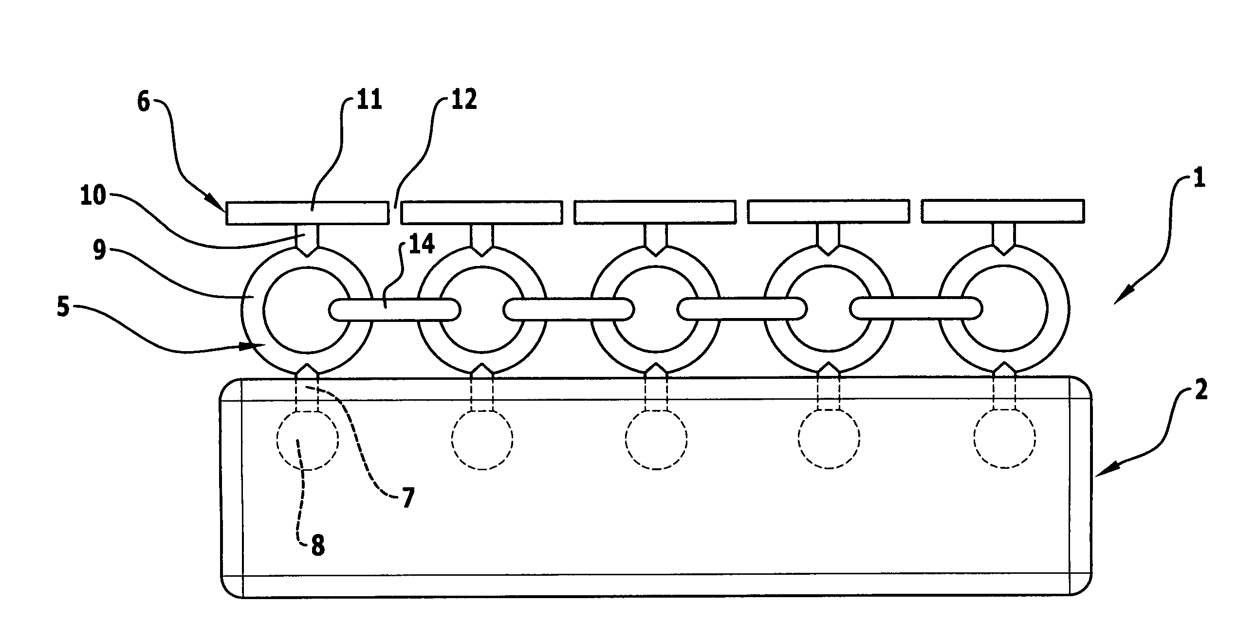
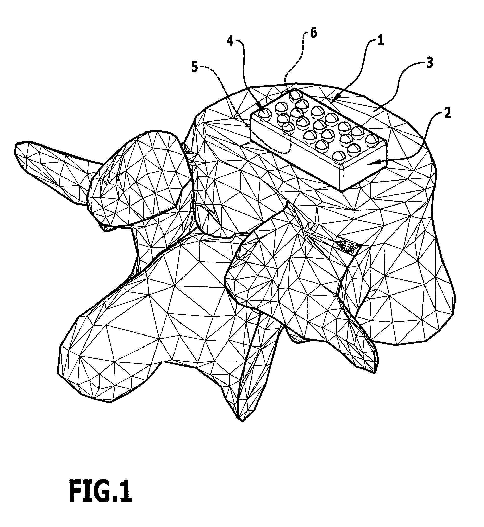
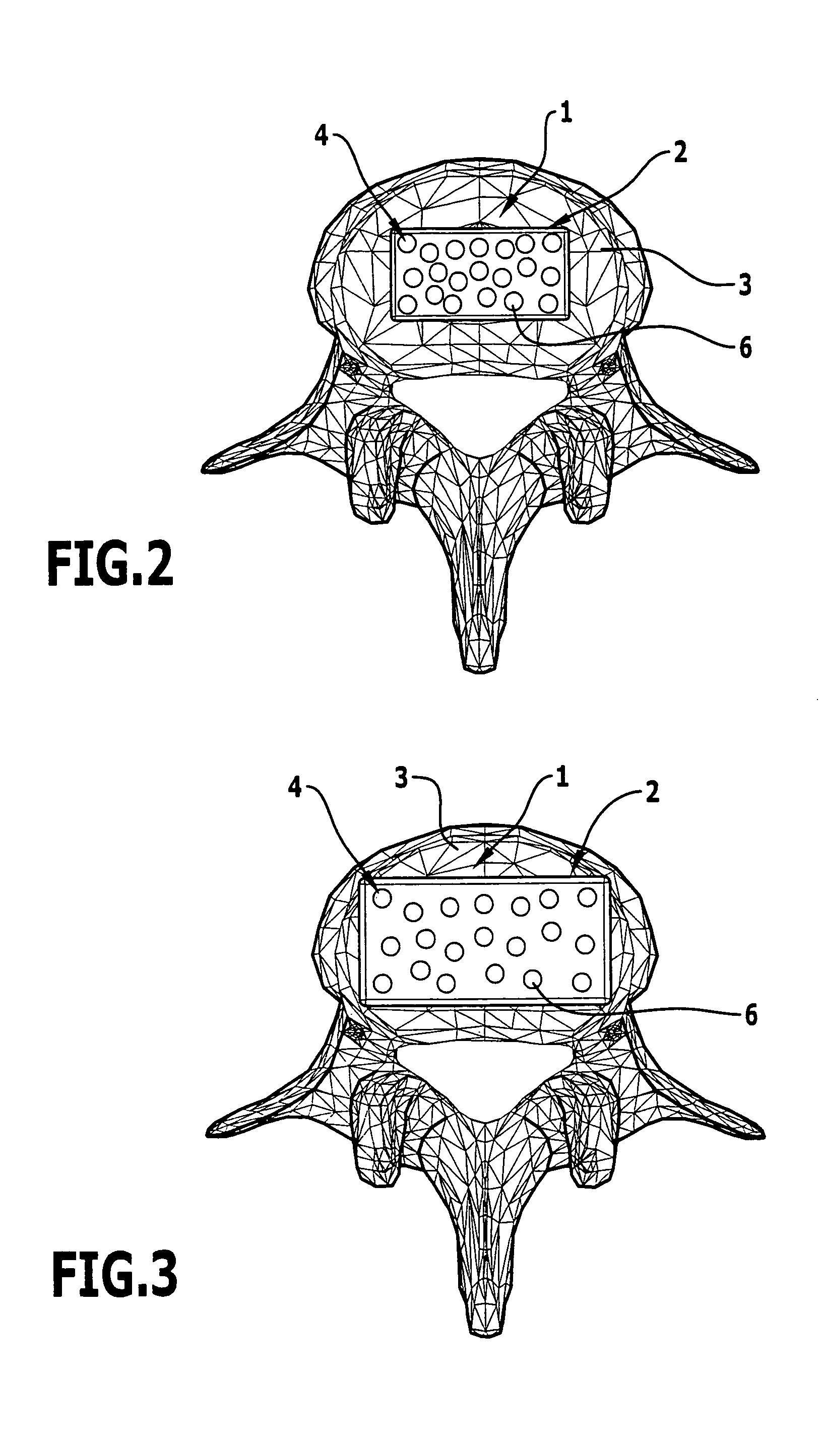
The intervertebral implant 1 represented in the drawings has as a principal part a core 2 made of a swellable material. In the embodiments represented in the drawings the core is in the shape of a cuboid, with other shapes also being usable, wherein the core 2 will as a rule be of a plate-shaped design with a flat top and a flat underside, although the external contour might alternatively be adapted to the external contour of a vertebral body 3.

The principal feature of the swellable material is that the volume of the swellable material in the dehydrated state, i.e. without a large liquid content, is small and increases considerably upon the absorption of liquid, in particular water. Thus, the core 2 expands when it is introduced into the body.

As swellable materials so-called hydrogels may be used. In this case, these may be in principle any non-degradable hydrophilic polymers, for example polyacrylic acid and its derivates such as polymethacrylic acid, polyacrylamide, polyacrylonitr...


PUM


Abstract

In order, in an intervertebral implant having a core made of a swellable material and having a vertebral-body locating face on its top and / or bottom side, which is connected to the swellable core, to reduce the shearing forces between the swellable core and the vertebral-body locating face during swelling of the swellable core, it is proposed that the vertebral-body locating face comprises a plurality of support elements, which are respectively anchored adjacent to one another and individually in the core, and a plurality of mutually separate locating elements, which are disposed adjacent to one another and outside of the core and which are carried by the support elements and are movable relative to one another in the plane of the vertebral-body locating face.

Description

The present disclosure relates to the subject matter disclosed in German patent application 10 2008 005 998.6 of Jan. 25, 2008, which is incorporated herein by reference in its entirety and for all purposes.BACKGROUND OF THE INVENTIONThe invention relates to an intervertebral implant having a core made of a swellable material and having a vertebral-body locating face on its top and / or bottom side, which is connected to the swellable core.Such an intervertebral implant is described for example in DE 20 2006 005 896 U1. Such an intervertebral implant comprises two end plates made of metal or plastics material, between which is disposed a hydrogel core that is made of a swellable material, which by absorbing water may increase its volume and hence bear a specific structural similarity to a natural intervertebral disk. In order to connect the swellable core to an integral, rigid end plate, in the known intervertebral implant the end plate is provided with thread- or rod-shaped anchoring...

Claims


Application Information

Patent Timeline
Patent Type & Authority Patents(United States)
IPC IPC(8): A61F2/44
CPCA61F2/442A61F2002/30075A61F2002/30153A61F2002/302A61F2002/30242A61F2002/30245A61F2002/30261A61F2002/30537A61F2002/30579A61F2002/30647A61F2002/30841A61F2002/30889A61F2002/30892A61F2210/0061A61F2230/0019A61F2230/0065A61F2230/0071A61F2230/0082A61F2250/0004
Inventor BEGER, JENSWAGNER, CECILEHAAS, ALEXANDER
Owner AESCULAP AG
Why Eureka
Try Eureka