Apparatus for decelerating and temporarily accumulating hot rolled product

a technology of accumulating and decelerating products, applied in the field of accumulators, can solve the problems of affecting the speed of vsub>1 /sub>, sudden and random variations, and affecting the smoothness of the drum surface,

Inactive Publication Date: 2011-09-27
SIEMENS IND INC
View PDF21 Cites 5 Cited by
  • Summary
  • Abstract
  • Description
  • Claims
  • Application Information

AI Technical Summary

Benefits of technology

[0010]In accordance with one aspect of the present invention, a shroud is configured to partially encircle the drum. Rotatable interior rollers are circumferentially spaced around the interior of the shroud. The interior rollers are spaced radially from the drum surface and extend in parallel relationship with the drum axis. A circumferential gap in the shroud serves to accommodate reciprocal movement of the catcher in a direction parallel to the drum axis. Preferably, the interior rollers are staggered in the direction of the drum axis, with overlapping ends.
[0013]In accordance with still another aspect of the present invention, a means is provided for urging and controlling the ordered shifting of the helical formation of rings along the surface of the drum.

Problems solved by technology

In practice, however, velocity V1 may undergo sudden and random variations due to unsteady rolling conditions in the mill.
If the mill control system is incapable of reacting to such variations with sufficient speed, the diameters of the rings may either increase or decrease to an undesirable extent.
If the rings become too small, resulting in the product being tightly wound on the drum, the resulting frictional resistance will impede shifting of the rings along the drum surface.
On the other hand, if the rings become too large, the helical ring pattern may be upset, leading to difficulties in unwinding the product from the drum.

Method used


Image

  • Apparatus for decelerating and temporarily accumulating hot rolled product
  • Apparatus for decelerating and temporarily accumulating hot rolled product
  • Apparatus for decelerating and temporarily accumulating hot rolled product

Examples


Embodiment Construction

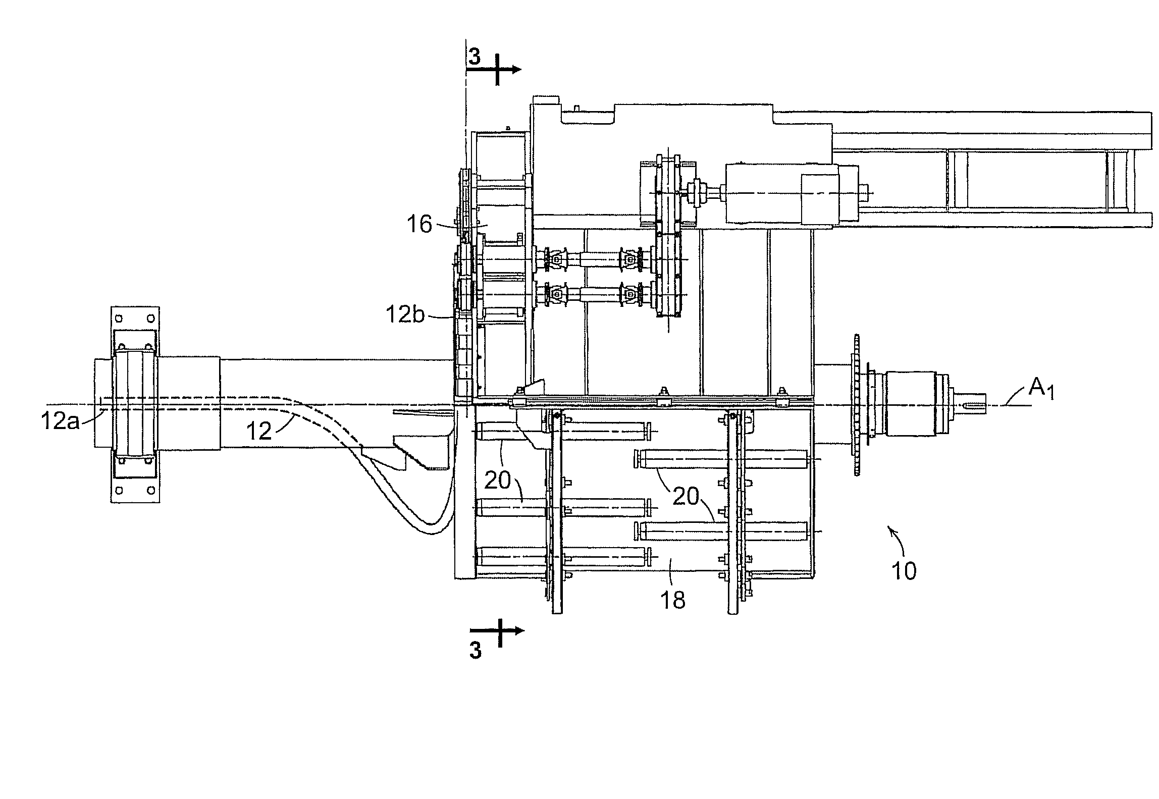
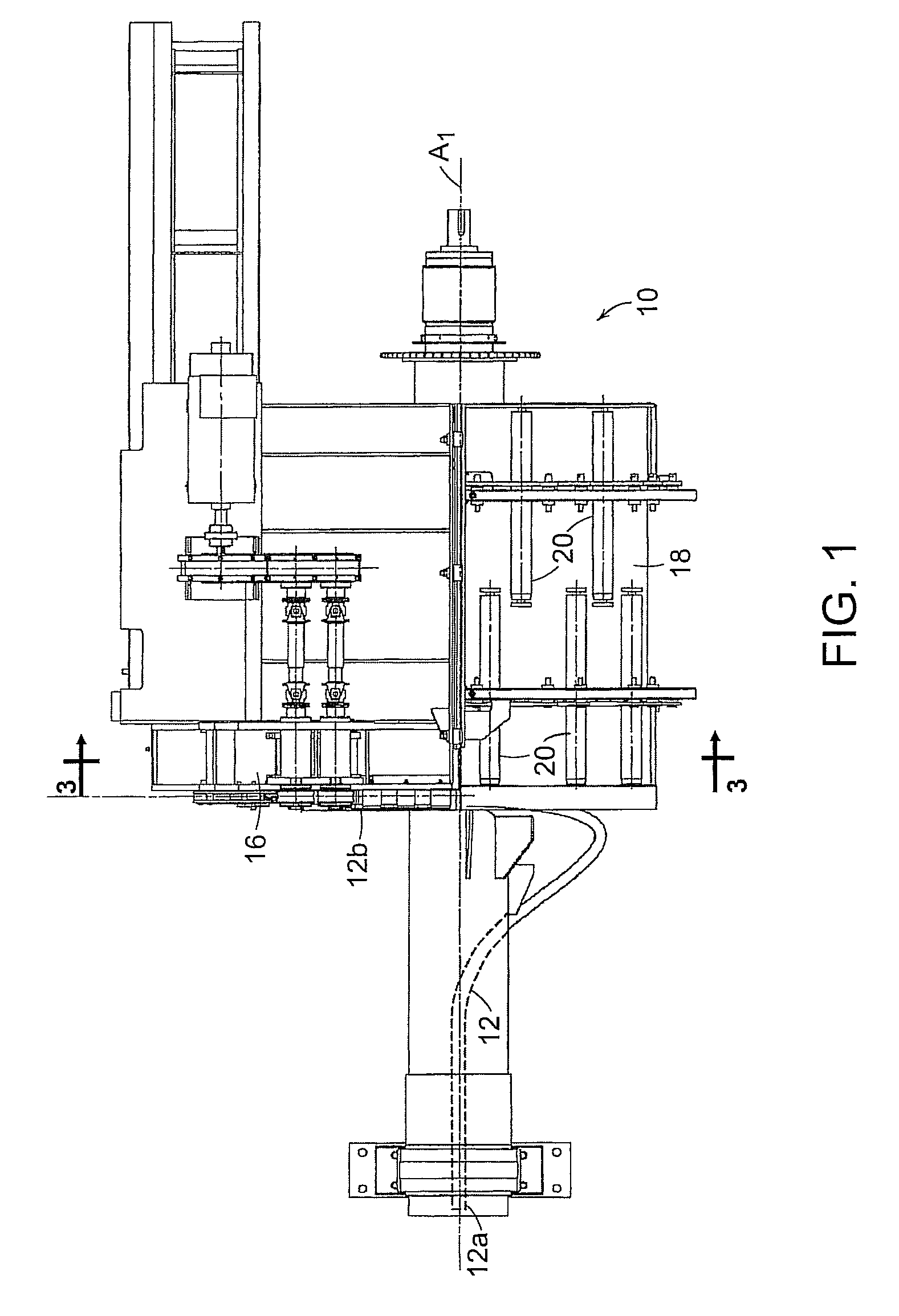
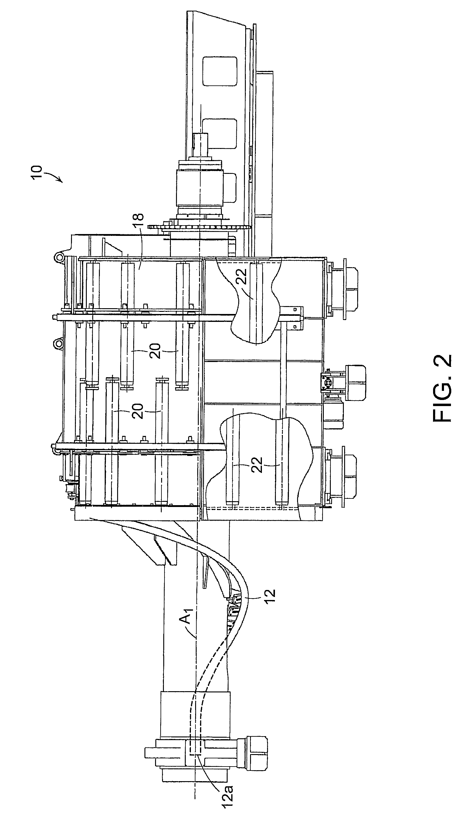
[0022]In accordance with a first aspect of the present invention, and as depicted in FIGS. 1-3, a stationary shroud 18 partially encircles the drum 14, leaving a circumferential gap between the locations designated at “X” and “Y”. The shroud carries a plurality of rotatable interior rollers indicated typically at 20. The rollers 20 are spaced radially from the drum surface and extend in parallel relationship to the drum axis A1. As can best be seen in FIGS. 1 and 2, the rollers 20 are preferably staggered in the direction of axis A1, with overlapping ends.

[0023]The gap between locations X and Y provides an unobstructed path for the movement, to and fro, of the catcher 16 during unwinding of the product from the drum.

[0024]In accordance with a second aspect of the present invention, a plurality of exterior rollers 22 are spaced around the surface of the drum 14. The rollers 22 also are staggered in the direction of the drum axis, with overlapping ends.

[0025]In the event that the diam...


PUM

PropertyMeasurementUnit
velocityaaaaaaaaaa
speedaaaaaaaaaa
velocity V2aaaaaaaaaa

Abstract

An apparatus is disclosed for decelerating and temporarily accumulating a hot rolled product moving longitudinally along a first axis at a first velocity V1. The apparatus comprises a curved guide with an entry end aligned with the first axis to receive the product, and with an exit end spaced radially from the first axis and orientated to deliver the product in an exit direction transverse to the first axis. The curved guide is rotatable about the first axis in a direction opposite to the exit direction of the product and at a speed at which its exit end has a second velocity V2 lower than V1 and such that the product is delivered from the exit end as a helical formation of rings and at a third velocity V3 equal to V1−V2. A cylindrical drum is arranged to axially receive the helical formation of rings and to rotate about the first axis in a direction opposite to the direction of rotation of the curved guide and at a speed such that the product is unwound from the drum at the third velocity V3. A receiver moves to and fro along a path parallel to the first axis to receive the product being unwound from the drum. A shroud is configured to partially encircle the drum, and rotatable interior rollers are circumferentially spaced around the interior of the shroud. The interior rollers are spaced radially from the surface of the drum and extend in parallel relationship with the first axis.

Description

BACKGROUND DISCUSSION[0001]1. Field of the Invention[0002]This invention relates to accumulators employed in rolling mills to temporarily accumulate and decelerate hot rolled products. Examples of such accumulators are described in U.S. Pat. Nos. 7,021,103 and 7,093,472, the descriptions of which are herein incorporated by reference.[0003]2. Description of the Prior Art[0004]In accumulators of the above-mentioned type, as depicted diagrammatically at 10 in FIGS. 8 and 9, a curved guide 12 has an entry end 12a aligned with a first axis A1 to receive a hot rolled product traveling at a first velocity V1. The guide has an exit end 12b spaced radially from axis A1 and orientated to deliver the product in an exit direction along a second axis A2 transverse to axis A1. The guide 12 is rotatable about axis A1 in a direction opposite to the exit direction of the product and at a speed at which its exit end 12b has a second velocity V2 lower than velocity V1. The product is thus delivered fr...

Claims


Application Information

Patent Timeline
Patent Type & Authority Patents(United States)
IPC IPC(8): B21D11/00
CPCB21C47/143B21C49/00B21B41/00B21C47/14
Inventor SHORE, T. MICHAELPALFREMAN, MATTHEW
Owner SIEMENS IND INC
Why Eureka
Try Eureka