Dust cup latch for cyclone separator vacuum

Inactive Publication Date: 2011-10-11
BISSELL INC
View PDF8 Cites 128 Cited by
  • Summary
  • Abstract
  • Description
  • Claims
  • Application Information

AI Technical Summary

Problems solved by technology

A mechanical issue addressed by the prior art is how to secure and release the reusable dirt- and dust-collecting receptacle (“dust cup”) that sits under the cyclone chamber.

Method used


Image

  • Dust cup latch for cyclone separator vacuum
  • Dust cup latch for cyclone separator vacuum
  • Dust cup latch for cyclone separator vacuum

Examples


Embodiment Construction

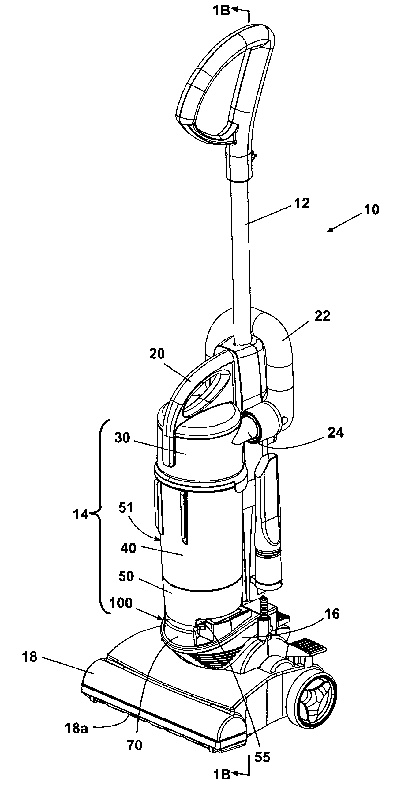
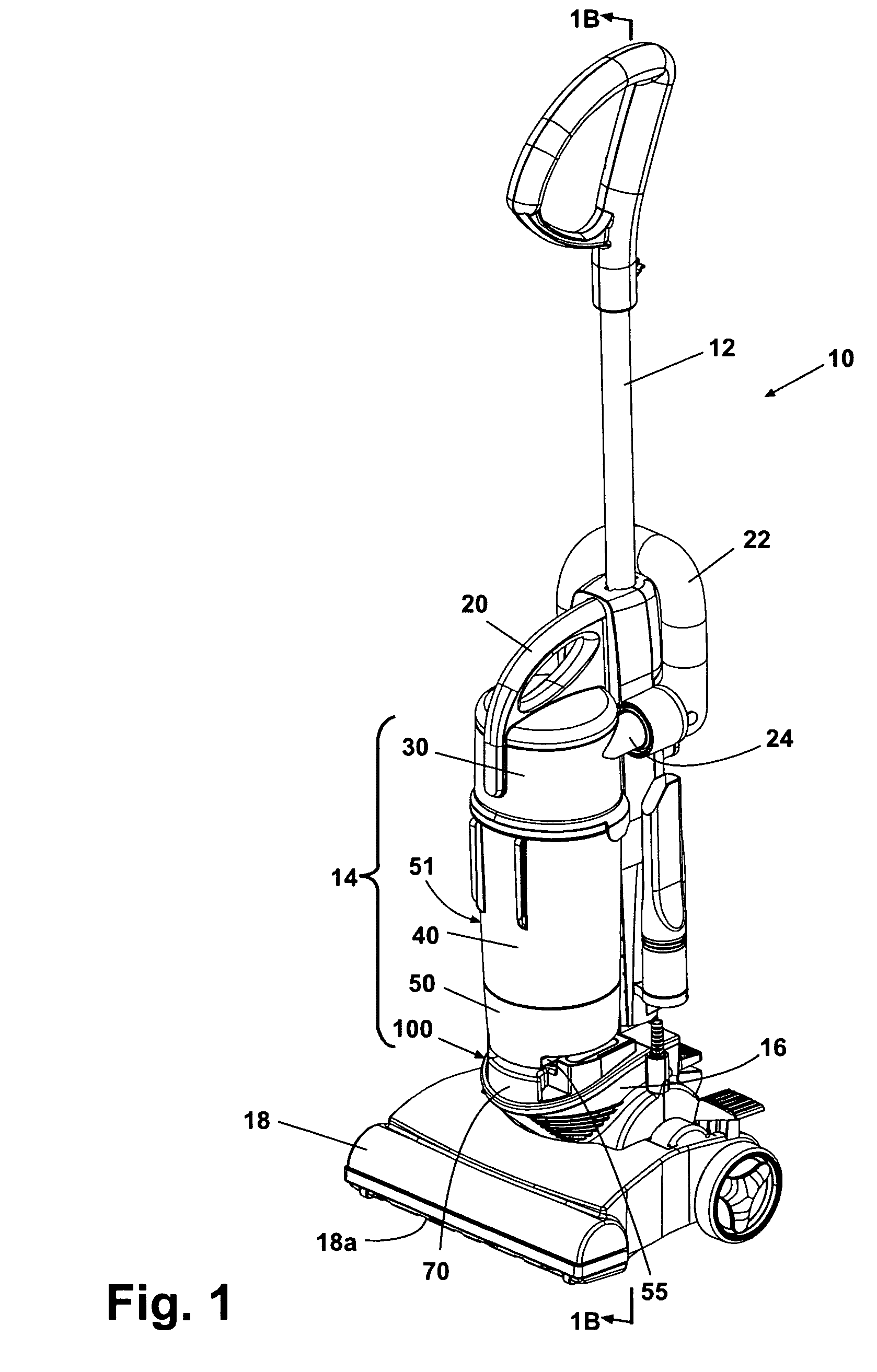
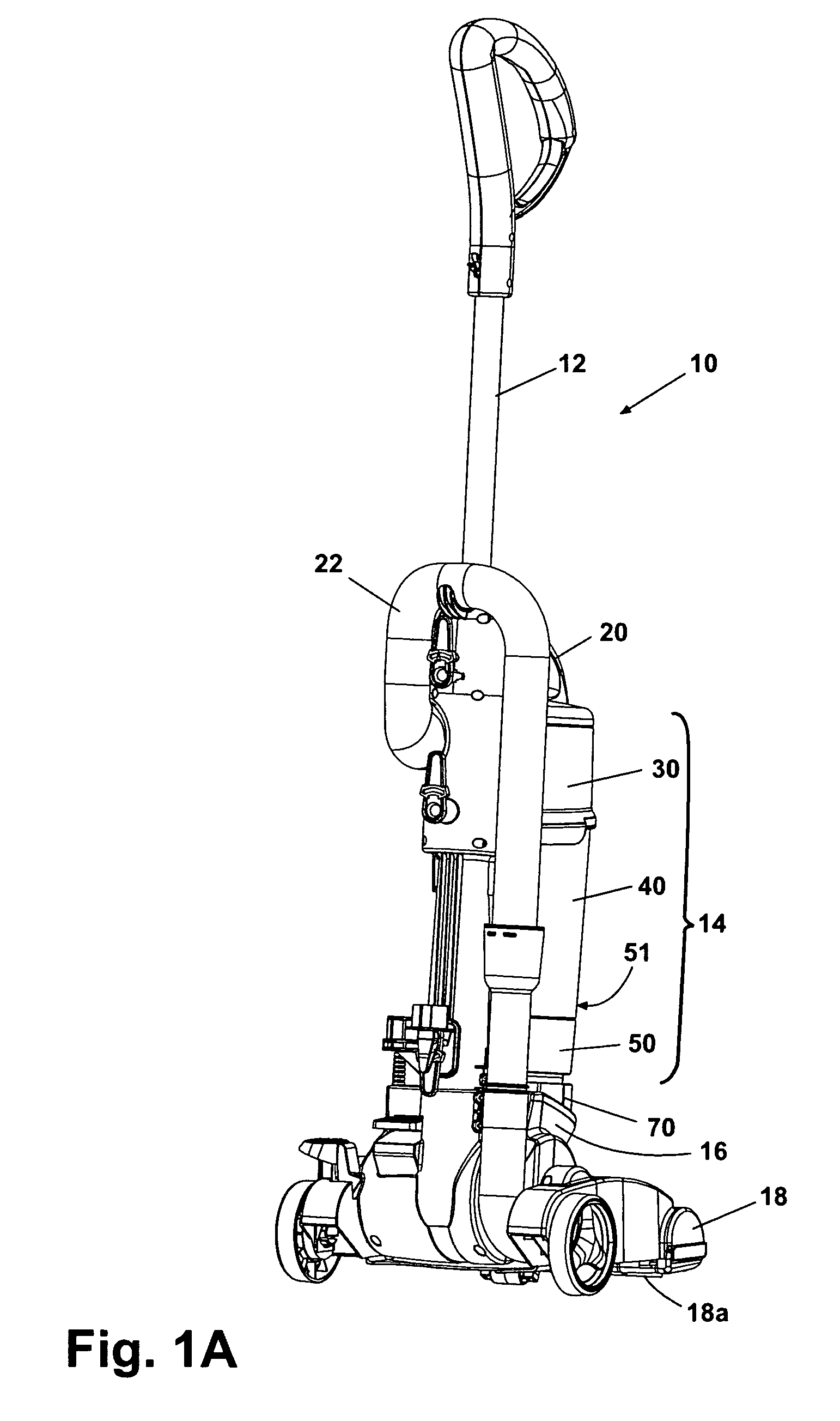
[0027]Referring first to FIGS. 1, 1A and 1B, a cyclone-separation type upright vacuum cleaner is shown at 10. The vacuum cleaner 10 has an operating handle 12; a cleaner body 14 including a cyclone chamber 30, a dust-collecting cup 40, and a filter case 50; a vacuum body 16 containing an internal suction-generating vacuum motor 16a (FIG. 1A); a brush housing 18 with a rotating brush 18a ; and a carry handle 20. A suction passage 22 is connected to receive dirt- and dust-laden air drawn in through the brush housing 18 in known manner and to deliver it in known cyclone-generating fashion to cyclone separator chamber 30 through a cyclone inlet 24.

[0028]The cyclone chamber 30 centrifugally separates dirt, dust, and other debris (hereafter collectively “dust”) from the swirling airflow in the chamber in known fashion. The separated dust moves to the outer wall of the cyclone chamber 30 via inertia and falls down through one or more peripheral passages 30a (FIG. 1B) in the lower end of cy...


PUM

PropertyMeasurementUnit
acute angleaaaaaaaaaa
diameteraaaaaaaaaa
movementaaaaaaaaaa

Abstract

A latching mechanism for the dust cup assembly on a bottom exit cyclone-separator vacuum cleaner, including a non-rotating annular seal member supporting the dust cup assembly above a discharge outlet, and a U-shaped slide lock member movable in and out underneath the dust cup assembly to raise and lower the seal member, thus raising and lower the dust cup assembly into and out of engagement with a cyclone separator chamber.

Description

CROSS-REFERENCE TO RELATED APPLICATIONS[0001]This application claims priority to U.S. Provisional Patent Applications Ser. No. 60 / 938,583, filed May 17, 2007, all of which is incorporated herein by reference.BACKGROUND OF THE INVENTION[0002]1. Field of the Invention[0003]The present invention is in the field of vacuum cleaners that use cyclone separators with removable debris-collecting receptacles.[0004]2. Description of Related Art[0005]Upright vacuum cleaners that use cyclone action to separate dust and dirt from the airflow through the vacuum cleaner are well known. A mechanical issue addressed by the prior art is how to secure and release the reusable dirt- and dust-collecting receptacle (“dust cup”) that sits under the cyclone chamber.[0006]U.S. Pat. No. 7,191,490 to Lee et al. discloses a top exit cyclone assembly including soil collection receptacle at a lower portion thereof and having a sliding groove formed on the bottom surface that confronts the floor of an accommodatio...

Claims


Application Information

Patent Timeline
Patent Type & Authority Patents(United States)
IPC IPC(8): A47L9/10
CPCA47L9/1691
Inventor GRIFFITH, AARON P.LUK, WING SHUNVANDER BAAN, GABRIEL S.
Owner BISSELL INC
Why Eureka
Try Eureka