Layered beam measurement apparatus

Inactive Publication Date: 2011-10-11
D2M INT
View PDF27 Cites 2 Cited by
  • Summary
  • Abstract
  • Description
  • Claims
  • Application Information

AI Technical Summary

Problems solved by technology

Yet the tape rule of all tape measures loses rigidity after being extended to some length.
However, a deeper profile in the tape rule results in difficulty in marking measurements on the surface being measured as the edges of the tape rule tend to curve up and away from the surface being measured.
This results in the user having to tilt the tape in order to accurately mark a desired measurement.

Method used


Image

  • Layered beam measurement apparatus
  • Layered beam measurement apparatus
  • Layered beam measurement apparatus

Examples


Embodiment Construction

Embodiments of the present invention described in the following detailed description are directed at virtual agents. Those of ordinary skill in the art will realize that the detailed description is illustrative only and is not intended to restrict the scope of the claimed inventions in any way. Other embodiments of the present invention, beyond those embodiments described in the detailed description, will readily suggest themselves to those of ordinary skill in the art having the benefit of this disclosure. Reference will now be made in detail to implementations of the present invention as illustrated in the accompanying drawings. Where appropriate, the same reference indicators will be used throughout the drawings and the following detailed description to refer to the same or similar parts.

In the interest of clarity, not all of the routine features of the implementations described herein are shown and described. It will, of course, be appreciated that in the development of any such...


PUM


Abstract

A new and improved tape rule that increases stiffness and standout length over standard tape rules is disclosed. The tape rule includes a primary rule and a secondary rule, the secondary rule providing increased strength. This invention can provide a variety of benefits, including increased blade flexibility while performing short extension related tasks, increased standout and reduced sag while performing tasks requiring longer extensions, reduced size and weight for tasks requiring the longest extensions and adds the ability to utilize alternate measurement methods or units and built in computational references.

Description

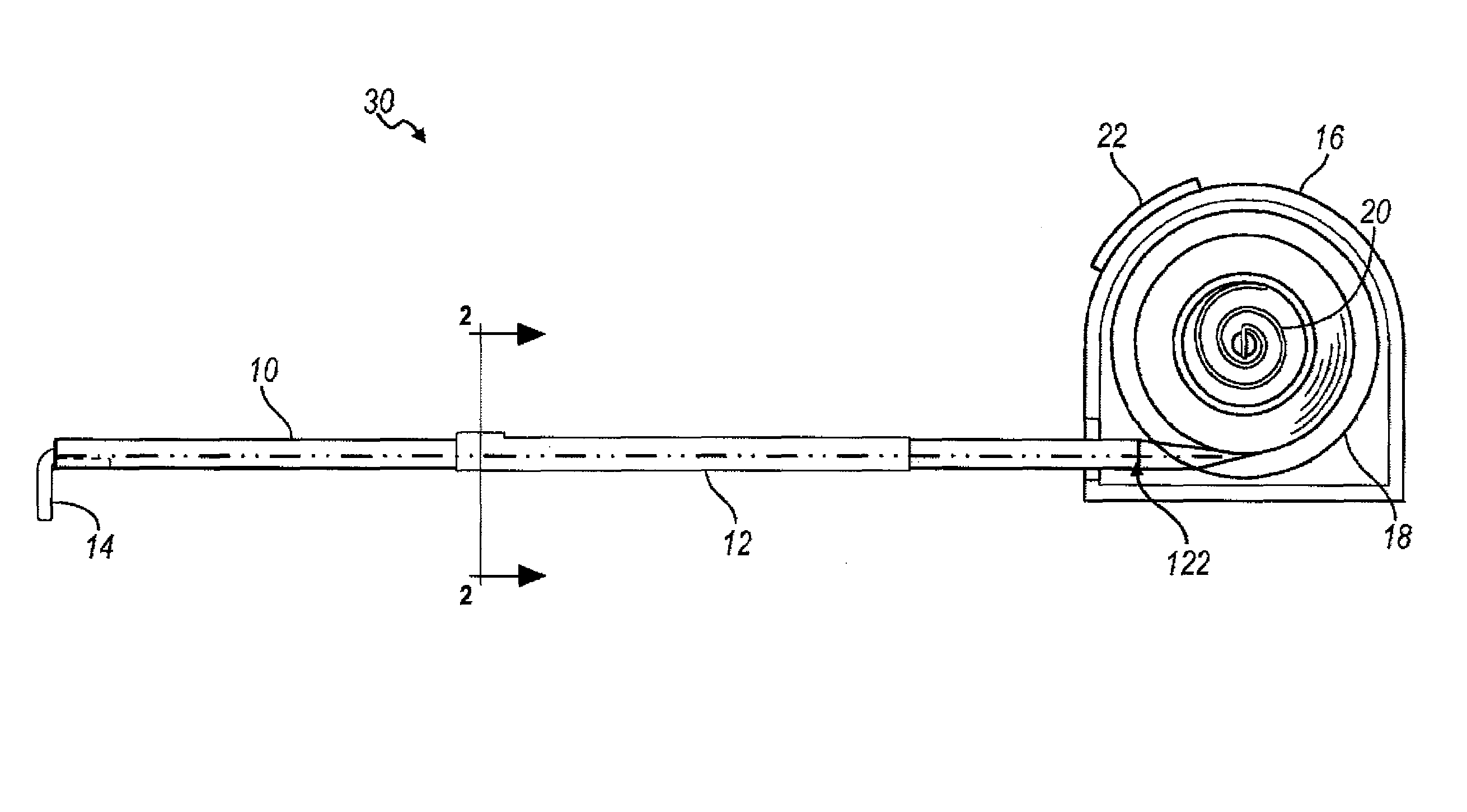
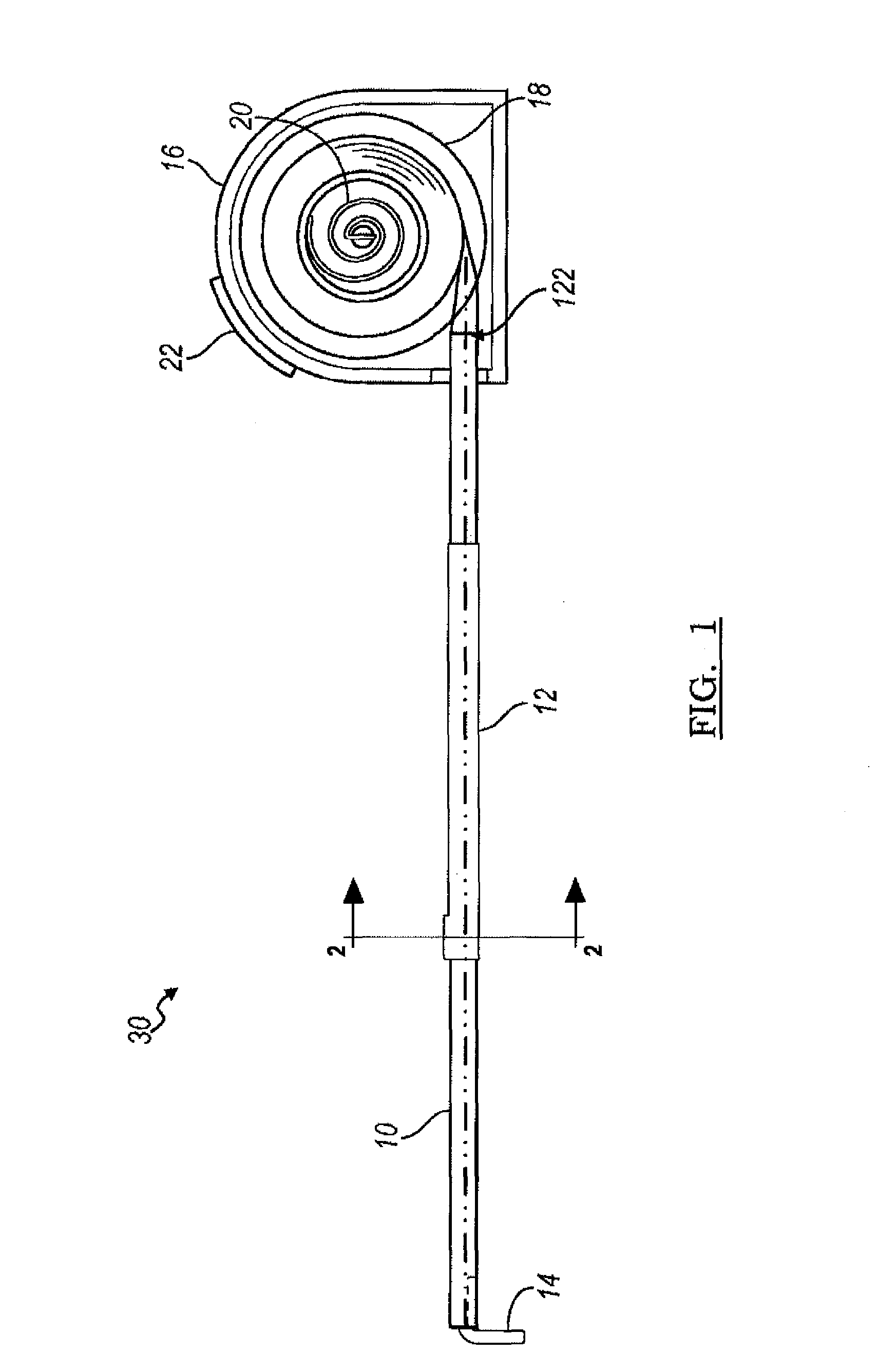
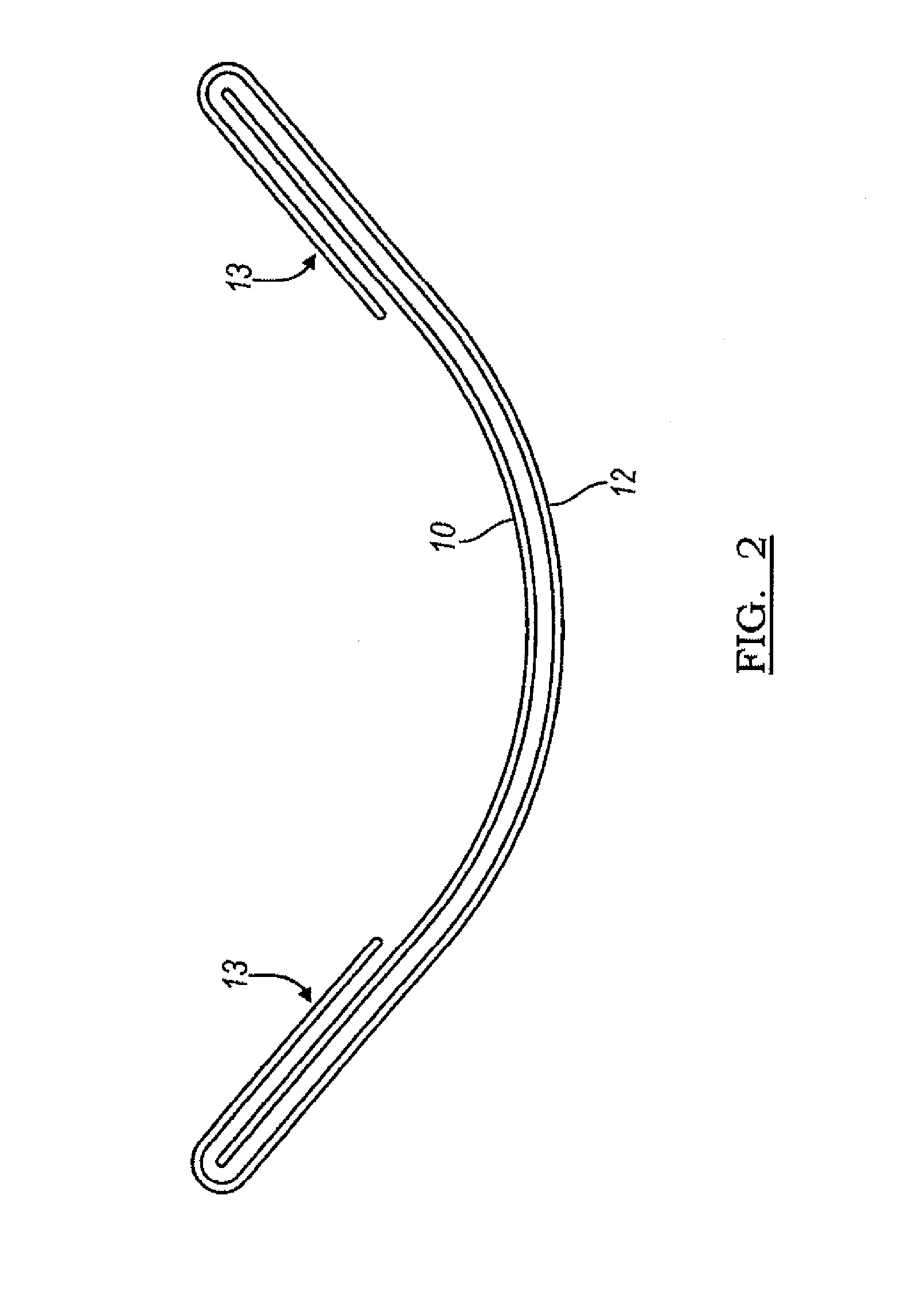
FIELD OF THE DISCLOSUREThe present disclosure relates generally to measurement tools, and in particular to tape measures.BACKGROUNDThe ideal tape rule would be perfectly flat and yet would not suffer from bending or folding when in the cantilevered position. Yet the tape rule of all tape measures loses rigidity after being extended to some length. To increase the rigidity of tape rules, tape rules of the prior art opt for either a wider tape rule or a deeper curve in the profile of the tape rule. However, a deeper profile in the tape rule results in difficulty in marking measurements on the surface being measured as the edges of the tape rule tend to curve up and away from the surface being measured. This results in the user having to tilt the tape in order to accurately mark a desired measurement.BRIEF DESCRIPTION OF THE DRAWINGSFIG. 1 is a cross-sectional diagram of a tape rule in accordance with the teachings of this disclosure;FIG. 2 is a cross sectional view of a tape rule asse...

Claims


Application Information

Patent Timeline
IPC IPC(8): G01B3/10
CPCG01B3/1082G01B2003/1051G01B3/1003
Inventor LAMB, BRIANTITZLER, DAVIDFLEMING, HEATHER
Owner D2M INT
Why Eureka
Try Eureka