Aggregate Delivery Unit

a technology of delivery unit and aggregate, which is applied in the direction of furnace, cap, borehole/well accessories, etc., can solve the problems of complex exploration, drilling and completion of hydrocarbon and other wells, large unit size, and high cos

Inactive Publication Date: 2009-03-26
SCHLUMBERGER TECH CORP
View PDF24 Cites 264 Cited by
  • Summary
  • Abstract
  • Description
  • Claims
  • Application Information

AI Technical Summary

Benefits of technology

[0017]A wireless control device is provided for controlling and monitoring the proppant delivery aspects of a hydraulic fracturing operation at an oilfield. The device includes a wireless transceiver coupled to a mobile body. A plurality of actuation levers are also coupled to the mobile body for directing release of proppant from interchangeable modular containers at the oilfield.

Problems solved by technology

Exploring, drilling and completing hydrocarbon and other wells are generally complicated, time consuming and ultimately very expensive endeavors.
This unit is generally very large due to the amount of proppant that may be required for any given fracturing operation and, when loaded may be extremely heavy in weight.
While it is advantageous to have all of the proppant delivered from a single unit with a single set of valves, this leads to the massive size of the unit as noted.
Thus, a tremendous amount of labor and space are required during manufacturing.
In addition, due to its large unitary configuration, there is no practical manner to monitor the reducing weight or volume of the different proppant compartments in an automated manner during an operation.
Furthermore, if proppant becomes unexpectedly depleted leaving the mixer empty, the entire operation may require shutting down.
In addition, reliance on visual inspection of the delivery unit results in a very imprecise monitoring of aggregate materials being employed for the fracturing operation.
Not only is this a very imprecise manner of monitoring the delivery mix, it also remains invisible to the operator until the delivery mix reaches the vicinity of the operator at the rear of the unit.
Overall, the operator is left with a proppant delivery unit that is massive, immobile, and requires a significant amount of space and unskilled man-hours to manufacture.
Furthermore, due to the configuration of the unit, the precision of the operation itself are both placed at risk.

Method used


Image

  • Aggregate Delivery Unit
  • Aggregate Delivery Unit
  • Aggregate Delivery Unit

Examples


Embodiment Construction

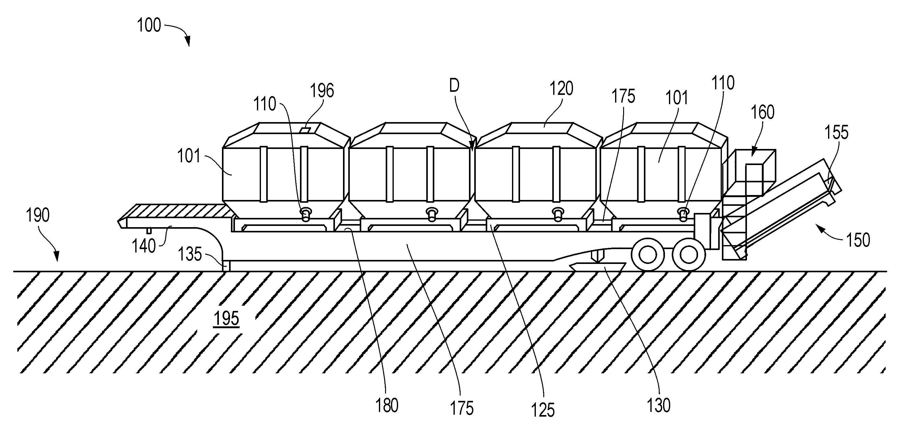
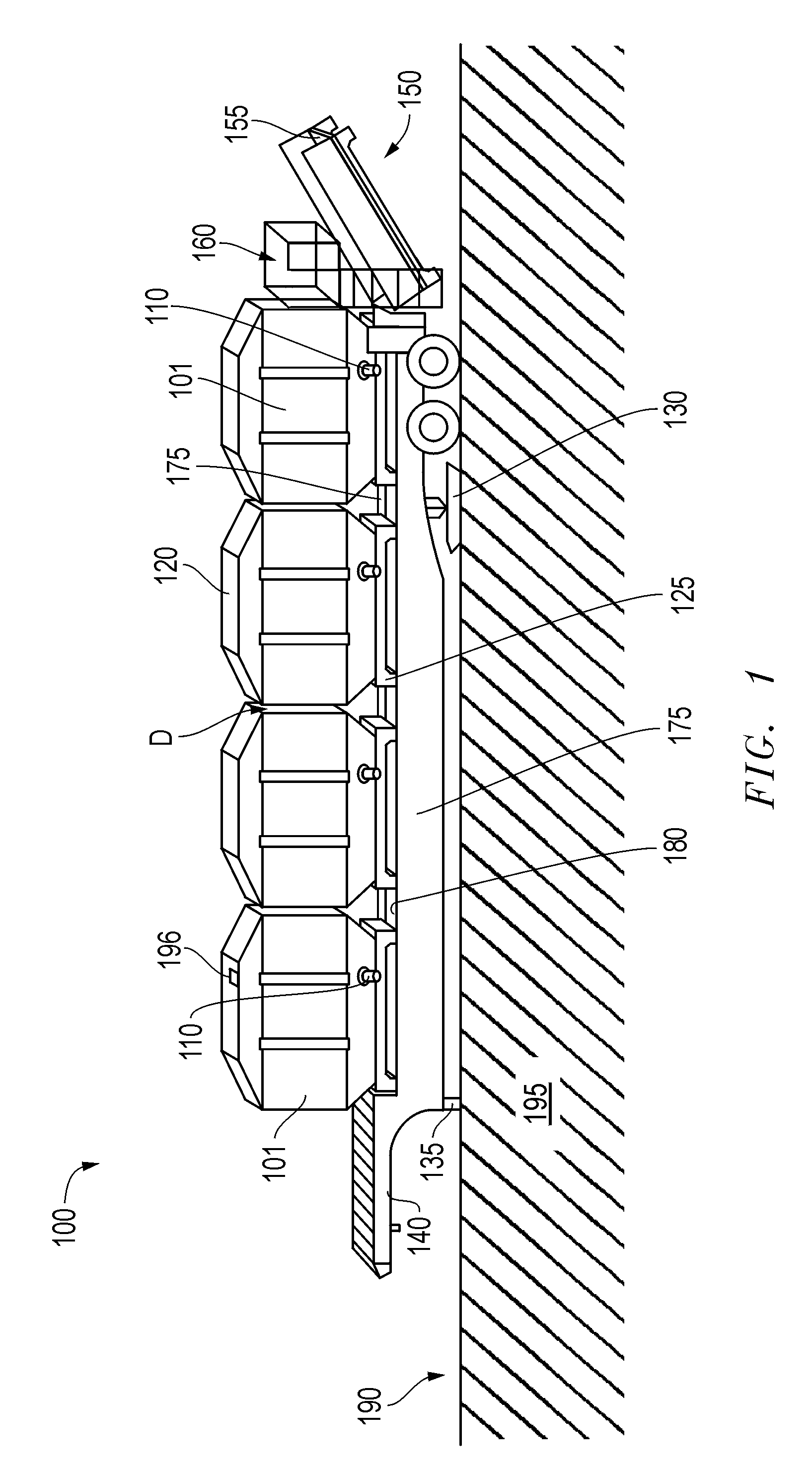
[0025]Embodiments are described with reference to certain aggregate delivery units for delivering proppant to a well at an oilfield during a fracturing operation. However, other types of aggregate may be accommodated by the units for a host of different industrial applications. For example, embodiments of aggregate delivery units described herein may be used in a variety of operations to store and deliver a host of other types of aggregates such as, but not limited to, cement, plastics, fertilizer, feed, and other agricultural products. Regardless, the aggregate delivery unit includes a modular container for housing the aggregate and / or means for monitoring delivery of the aggregate in substantially real-time during an operation.

[0026]Referring now to FIG. 1, a perspective view of an aggregate delivery unit 100 is depicted at an oilfield or wellsite location 190. The aggregate delivery unit 100 may have, but is not limited to, a capacity of 2,000-6,000 cubic feet provided by modular...


PUM


Abstract

A delivery unit for providing aggregate to a worksite, such as a wellsite location. The unit may include a mobile chassis for accommodating a plurality of modular containers which in turn house the aggregate. As such, a weight measurement device may be located between each container and the chassis so as to monitor aggregate levels within each container over time. The units may be particularly well suited for monitoring and controlling aggregate delivery during a fracturing operation at an oilfield. The modular containers may be of an interchangeable nature. Furthermore, a preferably wireless control device may be provided for monitoring and directing aggregate delivery from a relatively remote location.

Description

CROSS REFERENCE TO RELATED APPLICATION(S)[0001]This Patent Document claims priority under 35 U.S.C. §119(e) to U.S. Provisional Application Ser. No. 60 / 974,268, entitled Product Storage and Delivery Assembly, filed on Sep. 21, 2007, which is incorporated herein by reference in its entirety.BACKGROUND[0002]The statements in this section merely provide background information related to the present disclosure and may not constitute prior art.[0003]Embodiments described relate to aggregate delivery units. In particular, embodiments employing modular configurations of containers for housing aggregate are described. The containers may be well suited for housing aggregate in the form of proppant or other materials for use in oilfield operations.BACKGROUND OF THE RELATED ART[0004]The statements in this section merely provide background information related to the present disclosure and may not constitute prior art.[0005]Exploring, drilling and completing hydrocarbon and other wells are gener...

Claims


Application Information

Patent Timeline
Patent Type & Authority Applications(United States)
IPC IPC(8): B65G65/42E21B41/00B65D85/00B65G67/24B65G49/00
CPCE21B43/267B65D88/12B60P1/6418
Inventor KRENEK, DAVIDENGLAND, KEVIN W.
Owner SCHLUMBERGER TECH CORP
Why Eureka
Try Eureka