Cardiovascular anchoring device and method of deploying same

a technology of cardiac anchoring and cardiac valve, which is applied in the direction of angiography, surgical staples, therapy, etc., can solve the problems of chf worsening, hypoxemia, acidosis, and shortness of breath, and achieves the effects of reducing the risk of cardiac failur

Inactive Publication Date: 2006-12-12
PACESETTER INC
View PDF39 Cites 296 Cited by
  • Summary
  • Abstract
  • Description
  • Claims
  • Application Information

AI Technical Summary

Benefits of technology

[0011]Preferred embodiments of the present invention provide an anchoring device and a method of delivery which can effectively be used to deploy an anchoring mechanism for a variety of clinical applications. In one embodiment, an anchoring device is configured to cross the septum between the right and left atrium and trap itself between the two chambers such that a pressure sensing member is exposed to the left atrium. The device is configured in a manner that will allow it to position the pressure sensing member at a desired location relative to the septal wall while conforming to anatomical variations.
[0012]According to one embodiment, radiopaque markers can be provided on the anchor and / or the delivery and retrieval apparatus. One advantage of such markers is to enable fluoroscopic guidance of the devices during delivery and retrieval procedures.

Problems solved by technology

Transudation of fluid from the pulmonary veins into the pulmonary interstitial spaces, and eventually into the alveolar air spaces, is called pulmonary edema, and can cause shortness of breath, hypoxemia, acidosis, respiratory arrest, and death.
Problematically, however, over-treatment can lead to hypotension, renal impairment, hyponatremia, hypokalemia, worsening CHF, impaired mental functioning, and other adverse conditions.
Adding further to the problem of managing this condition is the fact that patients frequently miss scheduled doses by forgetting to take pills on time, running out of medications, or deciding to stop medications without consulting their physician.
This monitoring is itself problematic, however, in that it requires frequent visits with a caregiver, resulting in considerable inconvenience and expense.

Method used


Image

  • Cardiovascular anchoring device and method of deploying same
  • Cardiovascular anchoring device and method of deploying same
  • Cardiovascular anchoring device and method of deploying same

Examples


Embodiment Construction

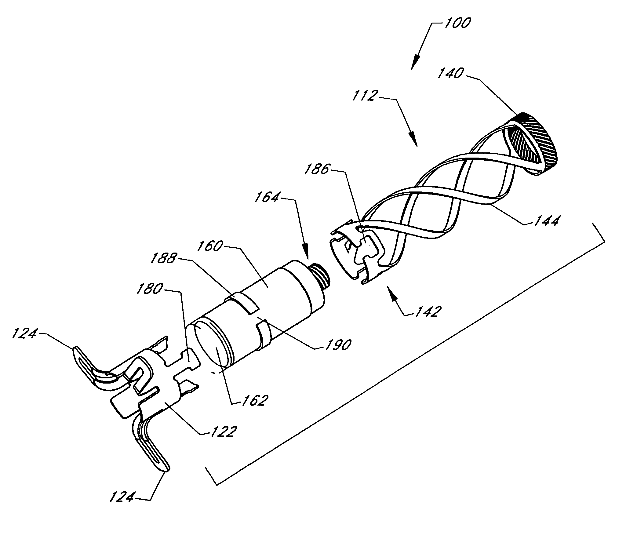
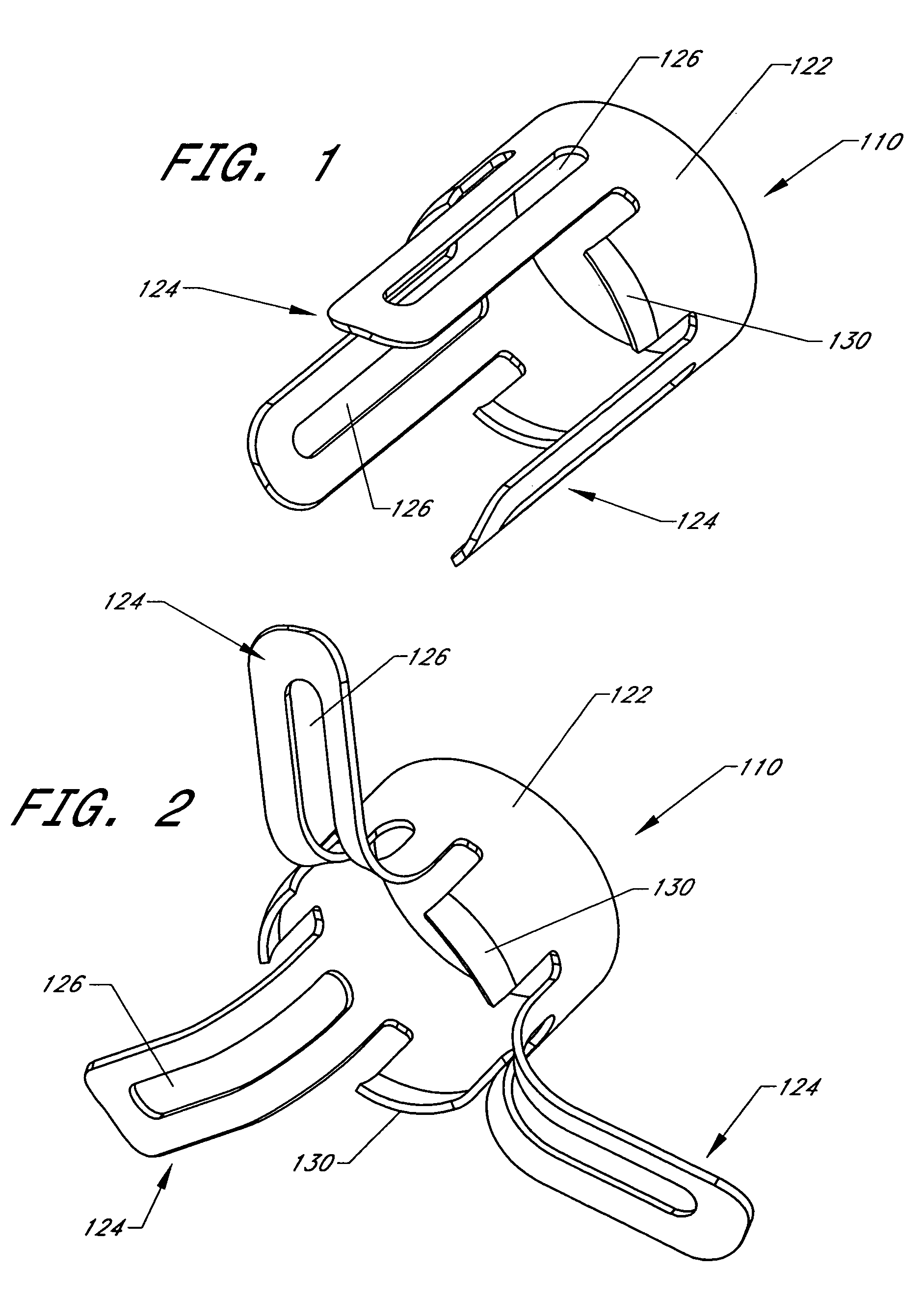
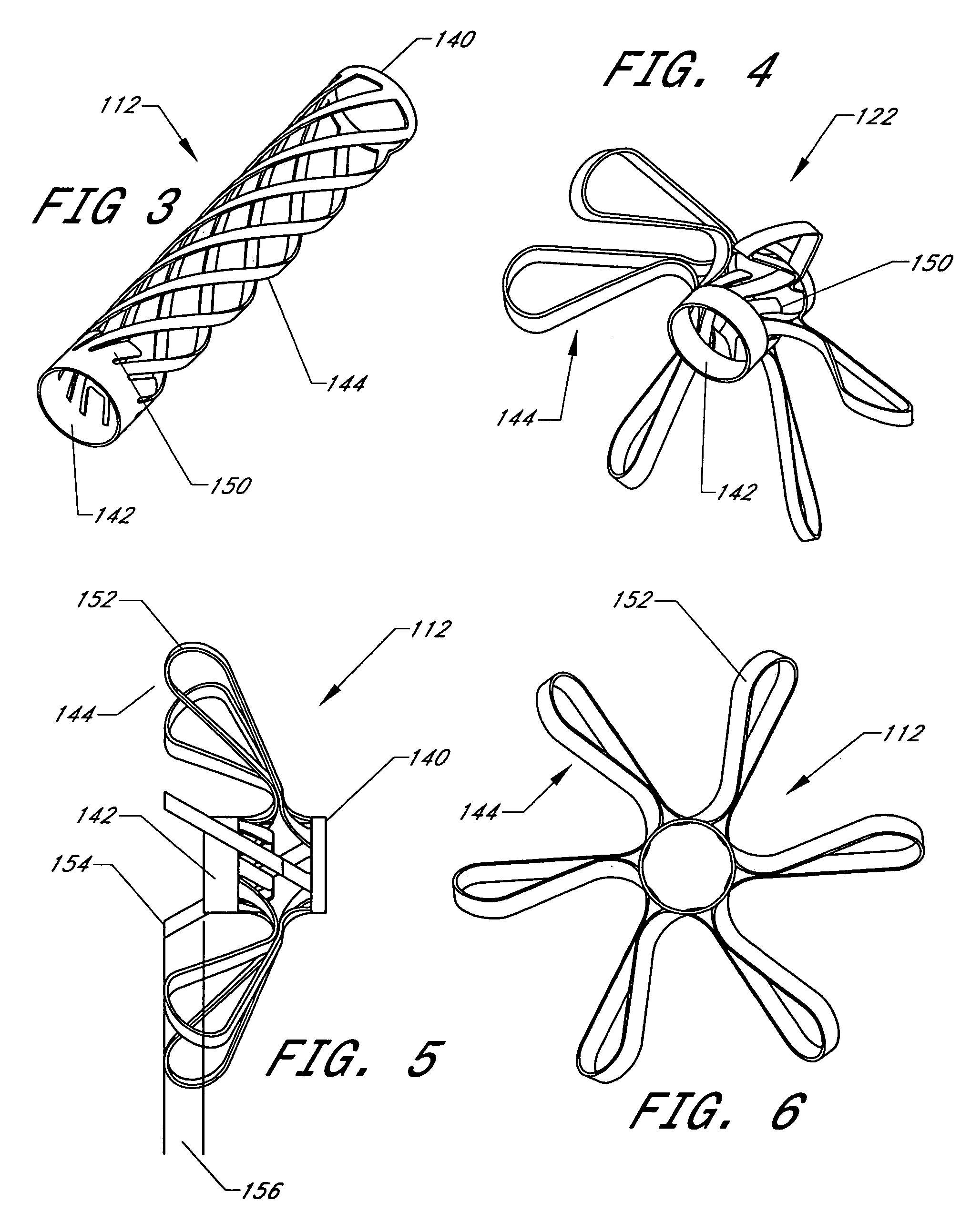
[0056]The following embodiments are described in relation to the placement of an anchoring and pressure measurement device within an atrial septum wall. The skilled artisan will recognize that certain aspects of the present invention can be applied to other applications as well. For example, the anchor devices described herein can be configured to anchor any suitable diagnostic and / or therapeutic implant to a wall of an organ within a patient. Therefore, it is intended that the scope of the present invention not be limited by the particular embodiments described below, but should be determined only by a fair reading of the claims.

[0057]Throughout the following description, the terms “proximal” and “distal” are used to describe relative positions, locations and / or orientations of various components. As used herein, the term “distal” is used in its ordinary sense, and generally refers to objects and locations that are further along a trans-vascular path. Similarly, the term “proximal”...


PUM


Abstract

An anchoring device and a delivery method thereof can effectively provide a means for securing an implant to a wall of an internal organ within a patient in a variety of clinical applications. In one embodiment, an anchoring device used to retain a cardiac pressure measurement device is provided. The device is implanted in the body by deforming it to a small cross section profile, sliding it through a low profile delivery device and ejecting from the delivery device at a targeted site. The anchoring mechanism, when ejected from the delivery device, reverts back to pre-formed configuration and engages opposite sides of an organ wall, thereby anchoring the implant in the organ wall.

Description

CROSS REFERENCE TO RELATED APPLICATIONS[0001]This application claims the benefit of U.S. Provisional Patent Application Ser. No. 60 / 413,758, which was filed on Sep. 26, 2002 and which is incorporated herein by reference.BACKGROUND[0002]1. Field of the Invention[0003]This invention relates generally to cardiovascular anchoring devices and methods of deploying the same.[0004]2. Description of the Related Art[0005]Heart failure is a cardiovascular condition in which the heart fails to sufficiently supply the body with the oxygen rich blood the body requires, either at exercise or at rest. Congestive heart failure (CHF) is heart failure accompanied by a build-up of fluid pressure in the pulmonary blood vessels that drain the lungs. Transudation of fluid from the pulmonary veins into the pulmonary interstitial spaces, and eventually into the alveolar air spaces, is called pulmonary edema, and can cause shortness of breath, hypoxemia, acidosis, respiratory arrest, and death.[0006]It is es...

Claims


Application Information

Patent Timeline
Patent Type & Authority Patents(United States)
IPC IPC(8): A61N1/37A61BA61B5/00A61B5/0215A61B5/04A61B5/042A61B17/00A61B17/064A61K9/22A61N1/05
CPCA61B5/0215A61B5/6882A61N1/057A61B5/042A61B5/145A61B17/064A61B2017/00243A61B5/283
Inventor WARDLE, JOHN L.EIGLER, NEAL L.
Owner PACESETTER INC
Why Eureka
Try Eureka