Enhanced sonde recognition

a sonde recognition and computer program technology, applied in the field of digital signal processing apparatus and computer program, can solve the problems of op-amp voltage noise, display readout which is prone to jitter, digital quantisation and spurious magnetic feedback, etc., and achieve the effect of enhancing snr

Inactive Publication Date: 2007-12-18
RADIODETECTION
View PDF6 Cites 48 Cited by
  • Summary
  • Abstract
  • Description
  • Claims
  • Application Information

AI Technical Summary

Benefits of technology

[0009]One of the key properties of sonde location is the quality and integrity of the signal processing. A poor SNR leads to unstable vector geometry and a display read-out which is prone to jitter. The invention can improve the clarity of the received signal at intermediate separations, making the readings more reliable and the display read-out less prone to jitter, thereby increasing the drilling speed and providing more efficient hardware deployment. Commercial sondes typically use a clock source with an accuracy of ˜20 ppm. Therefore to maintain the maximum SNR the receiver should phase lock to the sonde carrier frequency to follow any drift in frequency of the sonde.
[0022]In an embodiment of the invention, the frequency bins follow frequency variation of the magnetic signal produced by the sonde. As stated above the digital processing means comprises a phase feedback loop to allow the digital processing means to follow variations in the frequency of oscillation of the magnetic signal produced by the sonde. The frequency spectrum analyser is similarly phase locked to the sonde carrier frequency so that the entire bandwidth of the frequency spectrum analyser can ‘slide’ in the frequency domain. This ensures that the frequency bins of the frequency spectrum analyser are aligned with the fundamental carrier frequency and the harmonic frequencies, leading to enhanced SNR.

Problems solved by technology

A poor SNR leads to unstable vector geometry and a display read-out which is prone to jitter.
Other noise sources, such as op-amp voltage noise, digital quantisation and spurious magnetic feedback (a consequence of noise currents in the receiver) are unacceptable if they dominate the intrinsic antenna noise.

Method used


Image

  • Enhanced sonde recognition
  • Enhanced sonde recognition
  • Enhanced sonde recognition

Examples


Embodiment Construction

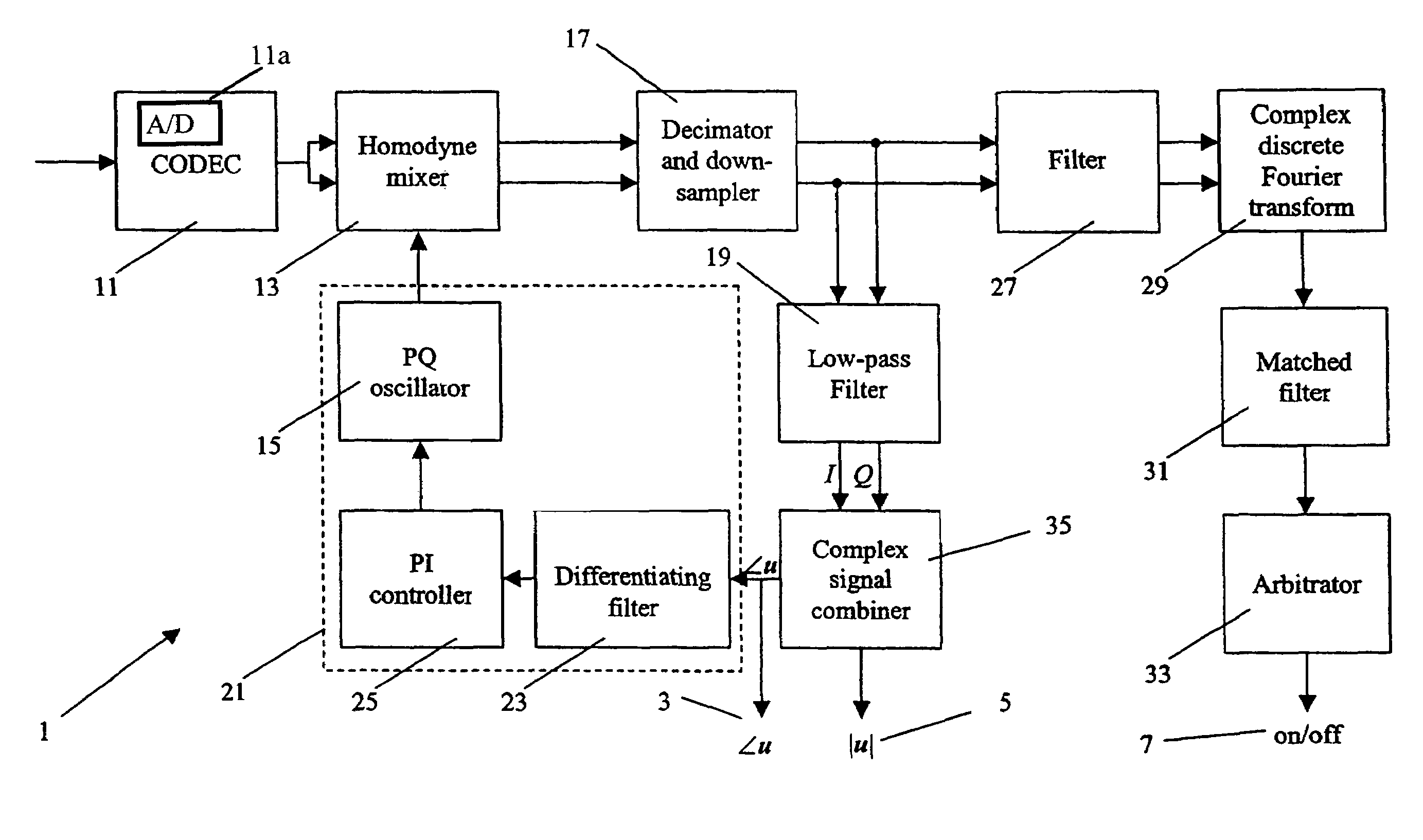
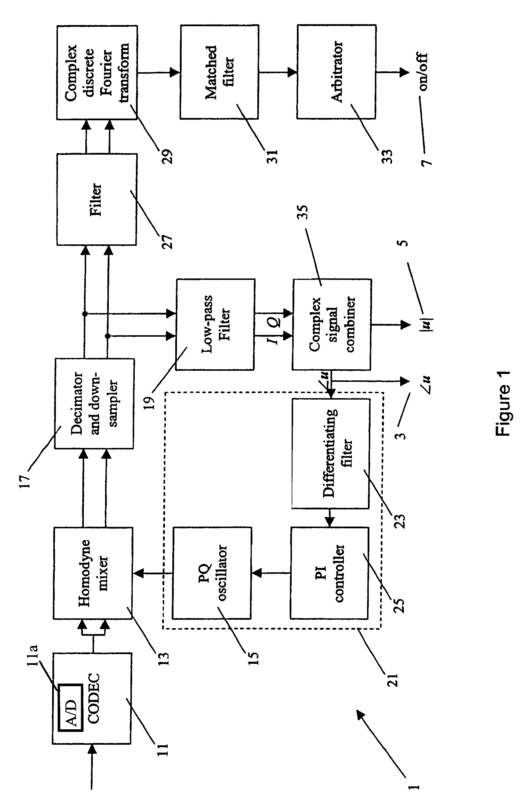
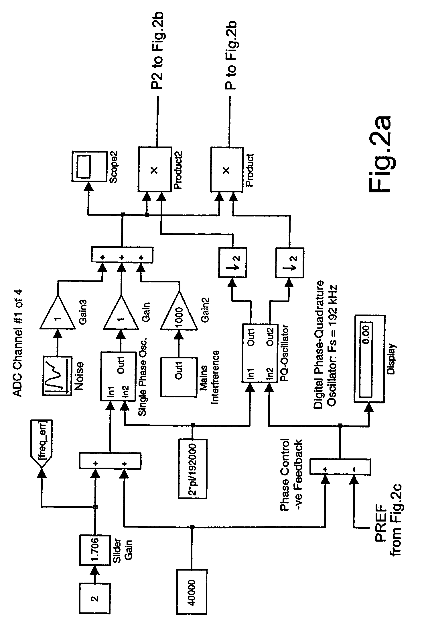
[0044]FIGS. 2a to 2d are parts of a Matlab® model of the digital signal isolator module embodying the invention which has been simplified in FIG. 1. A signal isolator module 1 is provided for each receive antenna. To provide accurate location of a sonde, four receive antennas are deployed. More than four receive antennas can be deployed to provide more accurate geometrical resolution, but this would be more expensive, more power hungry and less responsive due to the additional processing required. The signal isolator modules 1 of the detector simultaneously perform the signal processing of the received electromagnetic signals from the analogue outputs 9 of the associated antennas to produce a signal magnitude measurement 3 and a phase angle measurement 5 for the electromagnetic signal induced by the sonde in each antenna. The signal bandwidths are processed down to one of four selectable outputs (2.0, 1.0, 0.5 and 0.25 Hz) as is explained below. The selectivity requirement is −120 d...


PUM


Abstract

A detector for locating a sonde includes a plurality of antennas, an analogue to digital converter 11 and a digital signal processor to isolate the magnetic signal produced by the sonde. The digital signal processor includes a phase feedback loop 21 to allow the digital processing unit to follow variations in the frequency of oscillation of the magnetic signal produced by the sonde.

Description

FIELD OF THE INVENTION[0001]The present invention relates to apparatus and a computer program for and a method of digital signal processing, and in particular to apparatus and a computer program for and a method of sonde recognition.BACKGROUND OF THE INVENTION[0002]When laying a new utility cable or pipe underground, an underground drill can be used to avoid the need to dig and fill-in a trench. When performing such trenchless drilling, the drill operator must be aware of the exact location of the drill head, in order to steer the drill in the correct direction and to avoid buried utilities or underground structures.[0003]To locate the drill head, a sonde can be inserted therein. The sonde generates an alternating dipole magnetic field with a frequency of oscillation in the range 200 Hz to 83 KHz. At the lower of these frequencies, attenuation due to the drill bit enclosure and distortion due to ground effects are minimised. The magnetic signal can be modulated to transmit useful in...

Claims


Application Information

Patent Timeline
Patent Type & Authority Patents(United States)
IPC IPC(8): G06F19/00G01V3/08
CPCG01V3/26
Inventor ROYLE, JOHN MARK
Owner RADIODETECTION
Why Eureka
Try Eureka