Illumination device, method of assembling illumination device, and liquid crystal display device

a technology of illumination device and liquid crystal display device, which is applied in the direction of lighting and heating apparatus, planar/plate-like light guides, instruments, etc., can solve the problems of large power consumption, unsticking of led, and fear of solder cracking of led chip with printed substrate or cracking of led chip

Active Publication Date: 2011-10-11
EPSON IMAGING DEVICES CORP +1
View PDF16 Cites 33 Cited by
  • Summary
  • Abstract
  • Description
  • Claims
  • Application Information

AI Technical Summary

Benefits of technology

[0014]Herewith, when the light source unit is slidingly inserted in the housing, interference of the light source and the light guide plate can be prevented. Specifically, when an LED is used as the light source, occurrence of cracking of the solder fixing an LED chip with a printed substrate, or unsticking of the LED from the printed substrate can be prevented. In this manner, an exchange operation of the light source unit can be performed while preventing occurrence of a trouble such as a failing of lighting up the light source.
[0043]Herewith, the clearance between the light source and the light guide plate can be optimally kept by adjusting the position of the light source with respect to the light guide plate. As a result, lowering of luminance due to the clearance between the light source and the light guide plate that is too large can be restrained and stable light can be obtained.

Problems solved by technology

However, there is a disadvantage that, for example, power consumption is large.
However, as for an LED unit using an LED (light emitting diode) as a light source, there is a fear of occurrence of cracking of the solder fixing an LED chip with a printed substrate or unsticking of the LED chip from the printed substrate due to contact of the LED chip and the light guide plate when slide exchange is performed as the CFL.

Method used


Image

  • Illumination device, method of assembling illumination device, and liquid crystal display device
  • Illumination device, method of assembling illumination device, and liquid crystal display device
  • Illumination device, method of assembling illumination device, and liquid crystal display device

Examples


Embodiment Construction

[0058]Hereinafter, an embodiment of the invention will be described based on the accompanying drawings.

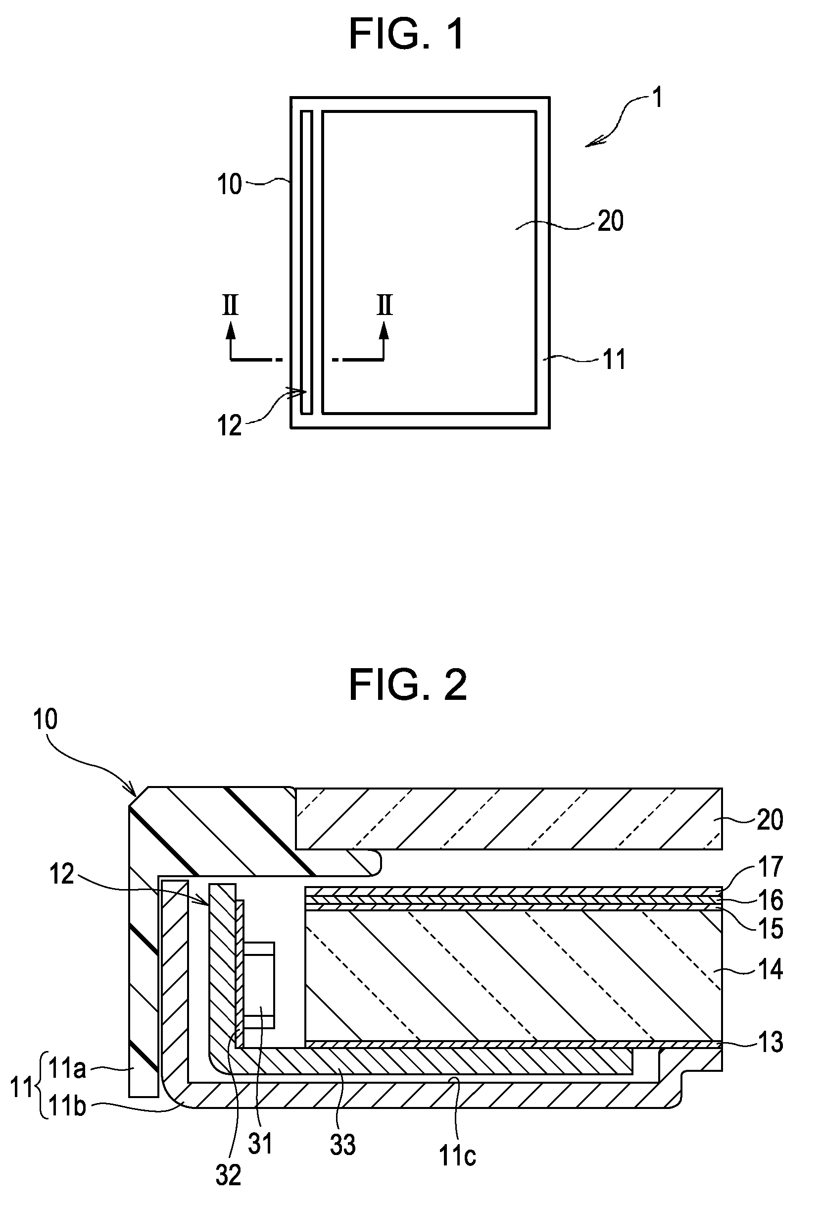
[0059]FIG. 1 is a plan view showing a liquid crystal module 1 constituting a liquid crystal display device according to a first embodiment.

[0060]The liquid crystal module 1 is equipped with a back light 10 and a liquid crystal panel 20, and the liquid crystal display device is equipped with the liquid crystal module 1, a driver IC for driving the liquid crystal panel 20, and a signal control circuit (not shown) thereof.

[0061]The back light 10 is equipped with a light source unit 12 and a case 11 formed by a resin or a plate (metal) for holding optical sheets to be described below. The back light 10 is disposed behind the liquid crystal panel 20 and illuminates the liquid crystal panel 20.

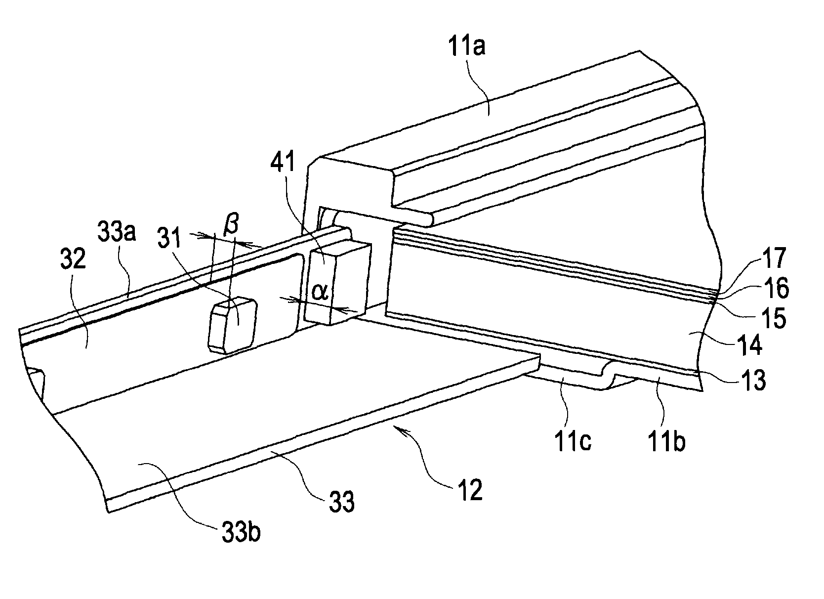
[0062]FIG. 2 is cross sectional view taken along the line II-II of FIG. 1.

[0063]As shown in FIG. 2, the case 11 of the back light 10 is constituted by combining an upper case 11a and a lower case 1...


PUM


Abstract

There is provided an illumination device equipped with a light guide plate, a light source unit having a plurality of point like light sources for supplying light to the light guide plate and a light source holding member for holding the point like light sources, the light source unit being disposed to oppose an edge face of the light guide plate, and a housing for holding the light guide plate and the light source unit. The light source unit is constituted so as to be inserted in and extracted from the housing by a slide mechanism that can be slid along the edge face of the light guide plate, and the light source unit is equipped with a spacer for assuring a gap between the edge face of the light guide plate and the light sources at a slide insertion side end of the light source unit with respect to the housing when the light source unit is slidingly inserted in the housing.

Description

[0001]The entire disclosure of Japanese Patent Application No. 2008-070793, filed Mar. 19, 2008 is expressly incorporated by reference herein.BACKGROUND[0002]1. Technical Field[0003]The present invention relates to an illumination device using a light source unit having a point like light source and a light guide plate, a method of assembling the illumination device, and a liquid crystal display device equipped with the illumination device.[0004]2. Related Art[0005]A liquid crystal display device is not a self-light emitting element that emits light by itself but a passive element that displays an image by some sort of light from outside. Accordingly, an illumination device such as a front light, a back light, or the like is used in the liquid crystal display device.[0006]There are two main types of the illumination device of the liquid crystal display device, a direct type capable of providing high luminance, high efficiency, and upsizing, and an edge light (side light) type for co...

Claims


Application Information

Patent Timeline
Patent Type & Authority Patents(United States)
IPC IPC(8): F21V7/04
CPCG02B6/0068G02B6/009G02B6/0091
Inventor TSUBAKI, YUICHI
Owner EPSON IMAGING DEVICES CORP
Why Eureka
Try Eureka