Auger grouted displacement pile

a displacement pile and grout technology, applied in the field of piles, can solve problems such as irregularities in the hol

Active Publication Date: 2011-10-11
STROYER BEN
View PDF45 Cites 27 Cited by
  • Summary
  • Abstract
  • Description
  • Claims
  • Application Information

AI Technical Summary

Benefits of technology

[0009]It is a further object of this invention to provide auger flighting that functions as a means to keep the grout column complete, consistent and continuous.

Problems solved by technology

The top section of the blade includes a deformation structure that cuts into the sides of the hole established by the lateral compaction plates, thus introducing irregularities into the hole.

Method used


Image

  • Auger grouted displacement pile
  • Auger grouted displacement pile
  • Auger grouted displacement pile

Examples


Embodiment Construction

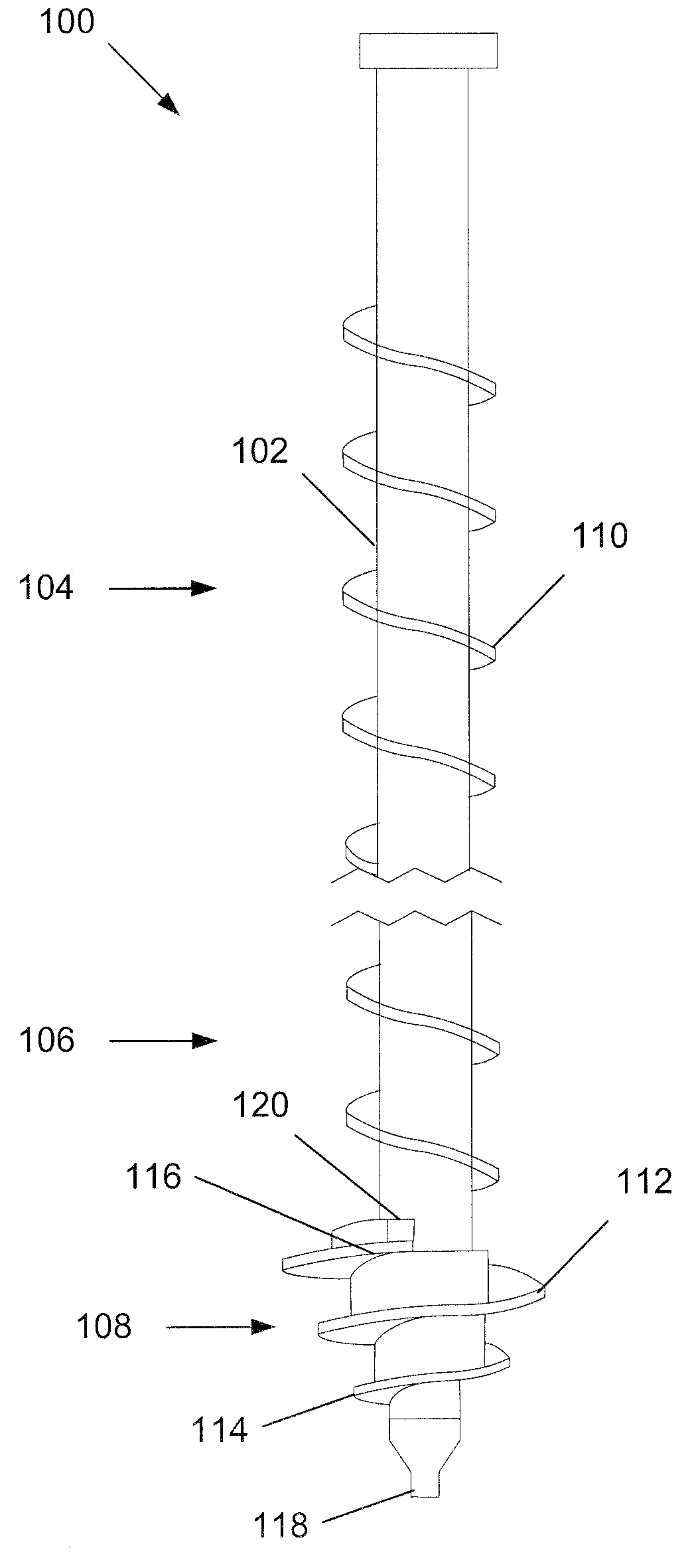
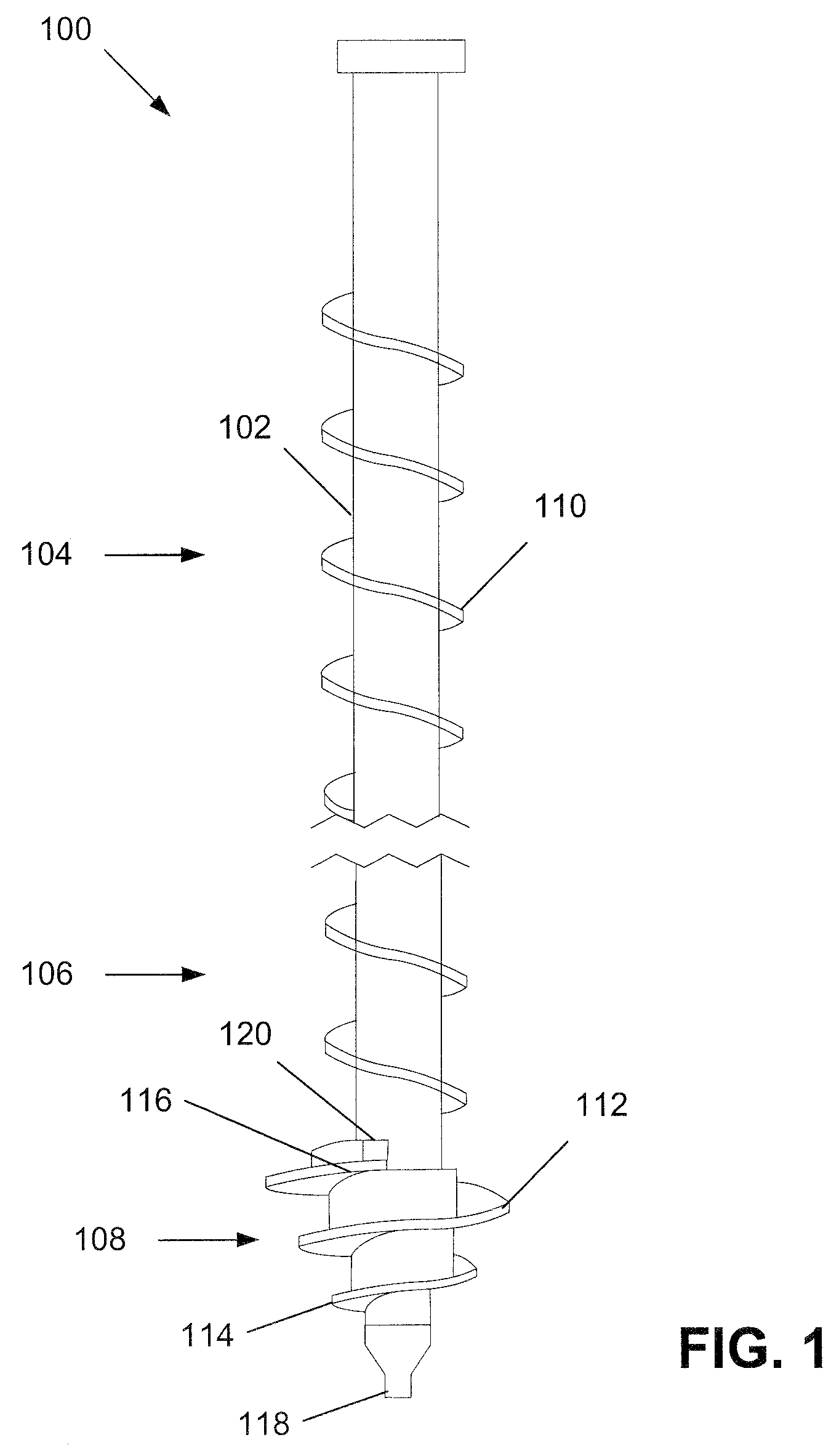
[0026]Referring to FIG. 1, auger grouted displacement pile 100 includes an elongated, tubular pipe 102 with a hollow central chamber 300 (see FIG. 3A), a top section 104 and a bottom section 106. Bottom section 106 includes a soil displacement head 108. Top section 104 includes an auger 110. Soil displacement head 108 has a blade 112 that has a leading edge 114 and a trailing edge 116. The leading edge 114 of blade 112 cuts into the soil as the pile is rotated and loosens the soil at such contact point. The soil displacement head 108 may be equipped with a point 118 to promote this cutting. The loosened soil passes over blade 112 and thereafter past trailing edge 116. Trailing edge 116 is configured to supply grout at the position where the soil was loosened. The uppermost rotation of blade 112 includes a deformation structure 120 that displaces the soil as the blade 112 cuts into the soil.

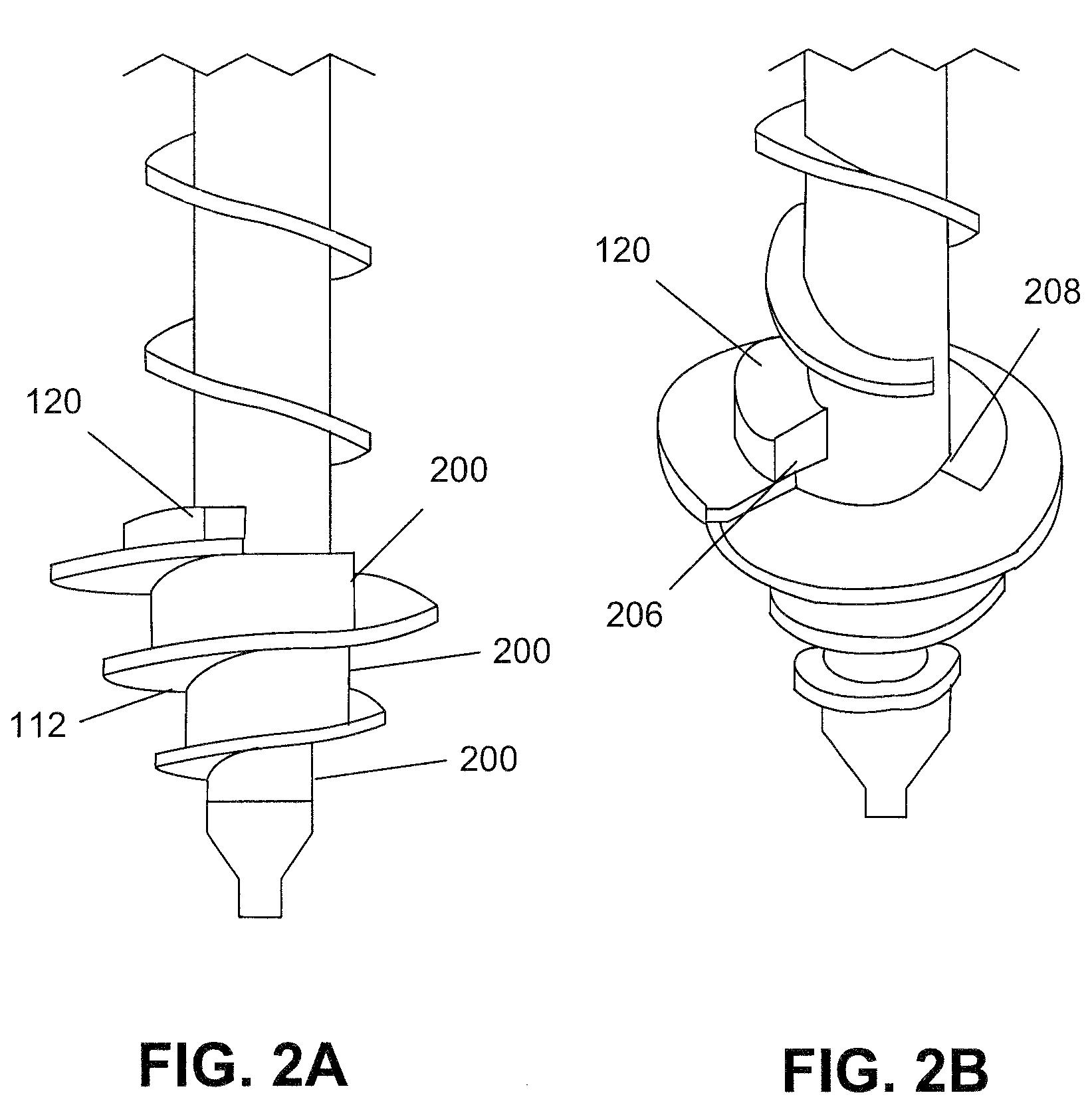
[0027]FIGS. 2A and 2B are side and perspective views of the bottom section 106. Bottom section...


PUM


Abstract

Disclosed in this specification is a method and apparatus for placing a helical pile in the soil with minimal disturbances to the soil. The helical pile has an elongated pipe with a central chamber. The pipe has a helical blade with an opening in the trailing edge of the blade where grout is extruded. The grout fills those portions of the soil which were disturbed by the blade. Advantageously, those portions of the soil which were not disturbed by the blade are not infused with grout.

Description

CROSS-REFERENCE TO RELATED APPLICATIONS[0001]This application is a continuation-in-part of U.S. application U.S. Ser. No. 11 / 852,858, filed Sep. 10, 2007, abandoned, which claims the benefit of U.S. Provisional Patent Application U.S. Ser. No. 60 / 843,015, filed Sep. 8, 2006. The aforementioned applications are incorporated herein by reference in their entirety.FIELD OF THE INVENTION[0002]This invention relates to piles, such as those used to support a boardwalk or a building foundation.BACKGROUND OF THE INVENTION[0003]Conventional piles are metal tubes having either a circular or a rectangular cross-section. Such piles are mounted in the ground to provide a support structure for the construction of superstructures. The piles are provided in sections, such as seven-foot sections, that are driven into the ground.[0004]Some piles have a cutting tip that permits them to be rapidly deployed. By rotating the pile, the blade pulls the pile into the ground, thus greatly reducing the amount ...

Claims


Application Information

Patent Timeline
Patent Type & Authority Patents(United States)
IPC IPC(8): E02D5/62
CPCE02D5/56E02D5/52
Inventor STROYER, BEN
Owner STROYER BEN
Why Eureka
Try Eureka