
Torque down pile substructure support system

a substructure support system and torque down technology, applied in the direction of bulkheads/piles, foundation engineering, construction, etc., can solve the problems of any standing structure, ground surrounding the pile to heave, and soil surrounding the pile to be compacted in various ways

Active Publication Date: 2006-09-07
DRILL TECH DRILLING & SHORING INC
View PDF12 Cites 29 Cited by
  • Summary
  • Abstract
  • Description
  • Claims
  • Application Information

AI Technical Summary

Problems solved by technology

When driving a foundation pile, the soil surrounding the pile may be compacted in various ways as well as disrupted by the seismic shocks of the pile driver itself.
When driving a pile into hard ground, earth displaced by the pile causes the ground surrounding the pile to heave.
All of these conditions can cause problems for any standing structures in the area of the pile being driven.
However, all these methods can prove either costly and / or slow to carry out in the field.
Furthermore, where the ground in a job site is deemed to be contaminated, any soil removed from the ground, such as that produced by an auger, must be disposed of properly presenting an additional problem and associated cost.
Although they do have certain advantages over other known systems, both of these drilling systems are obviously substantially more complex, and therefore more costly than the first several prior art systems discussed.

Method used


Image

  • Torque down pile substructure support system
  • Torque down pile substructure support system
  • Torque down pile substructure support system

Examples


Embodiment Construction

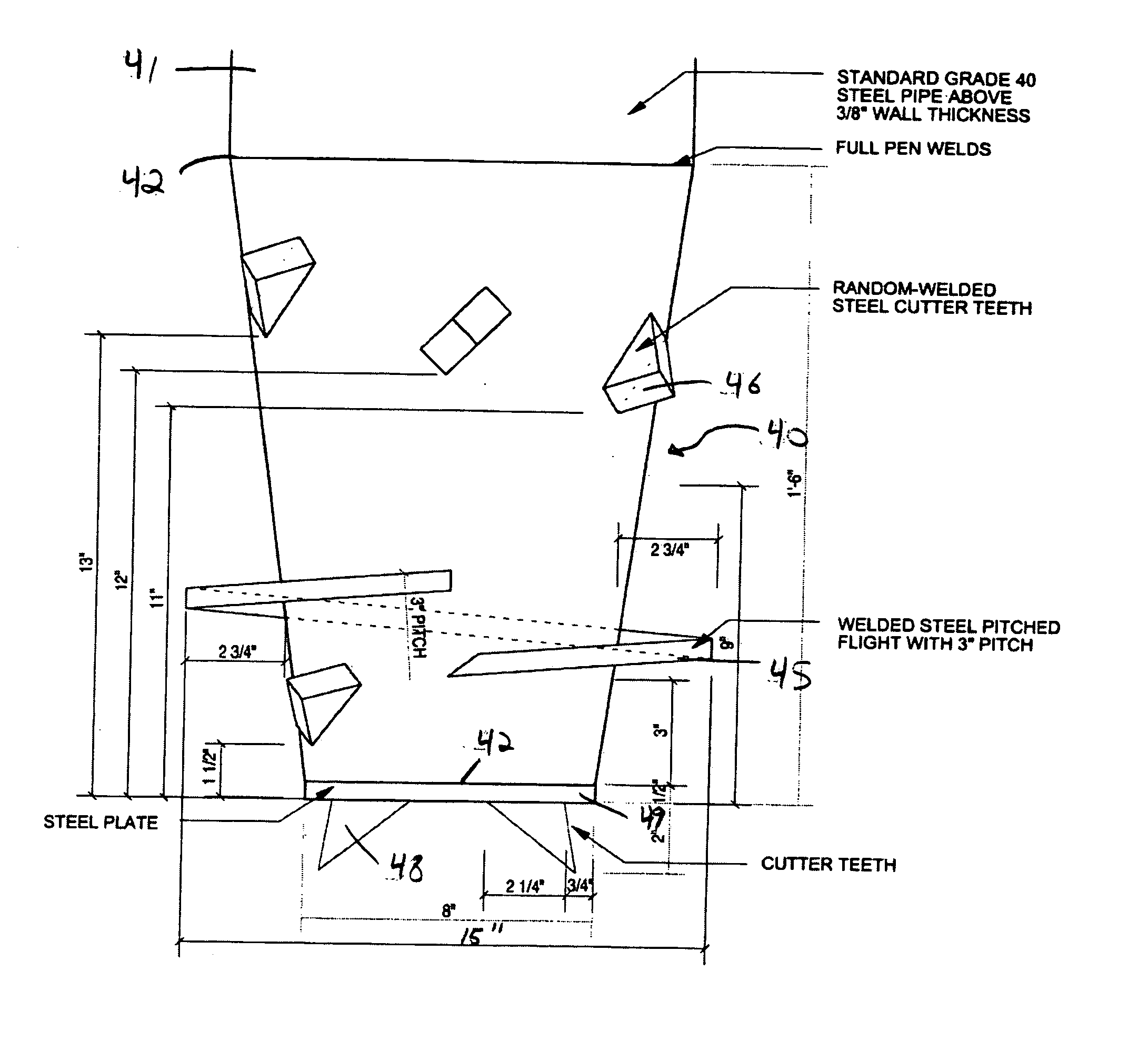
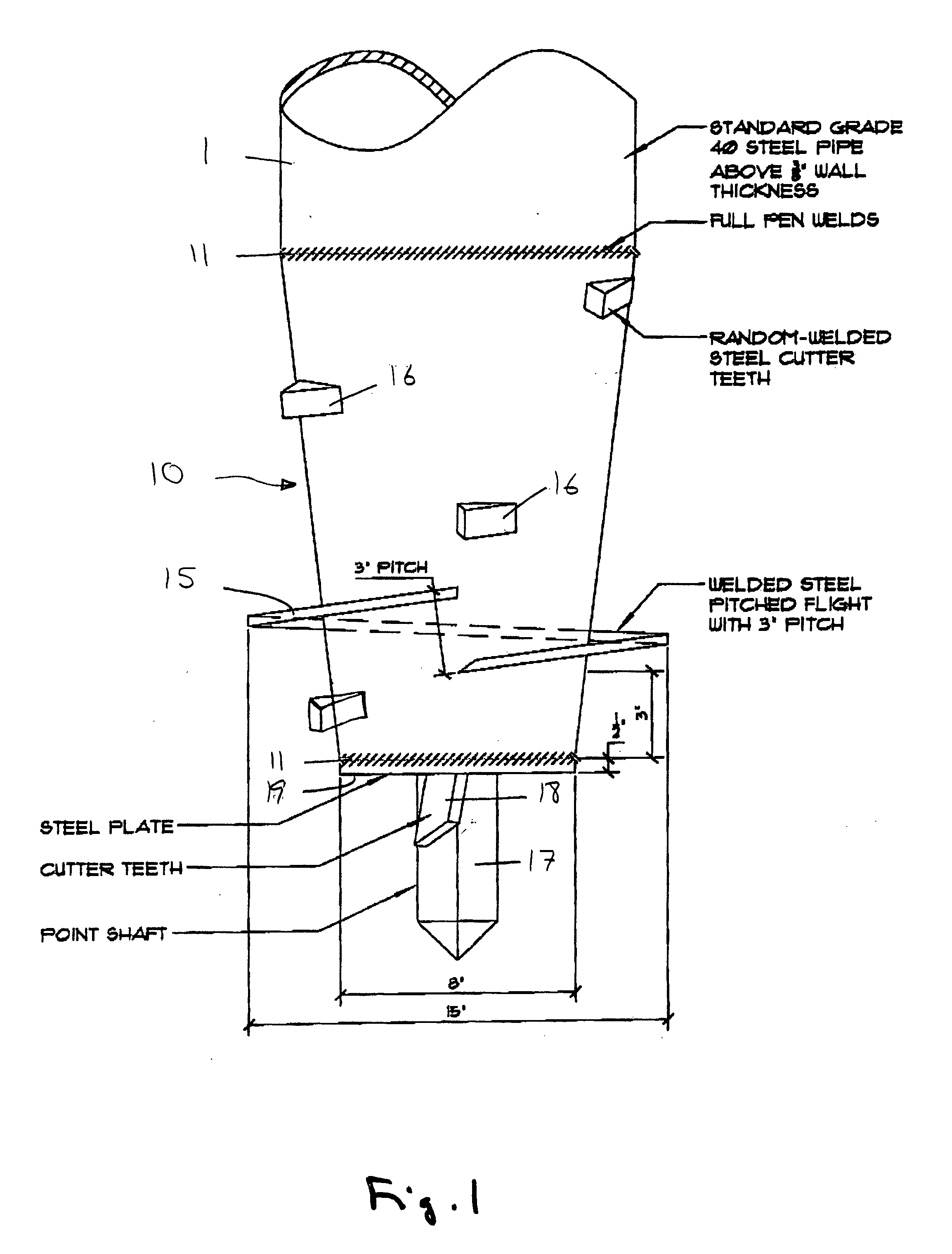
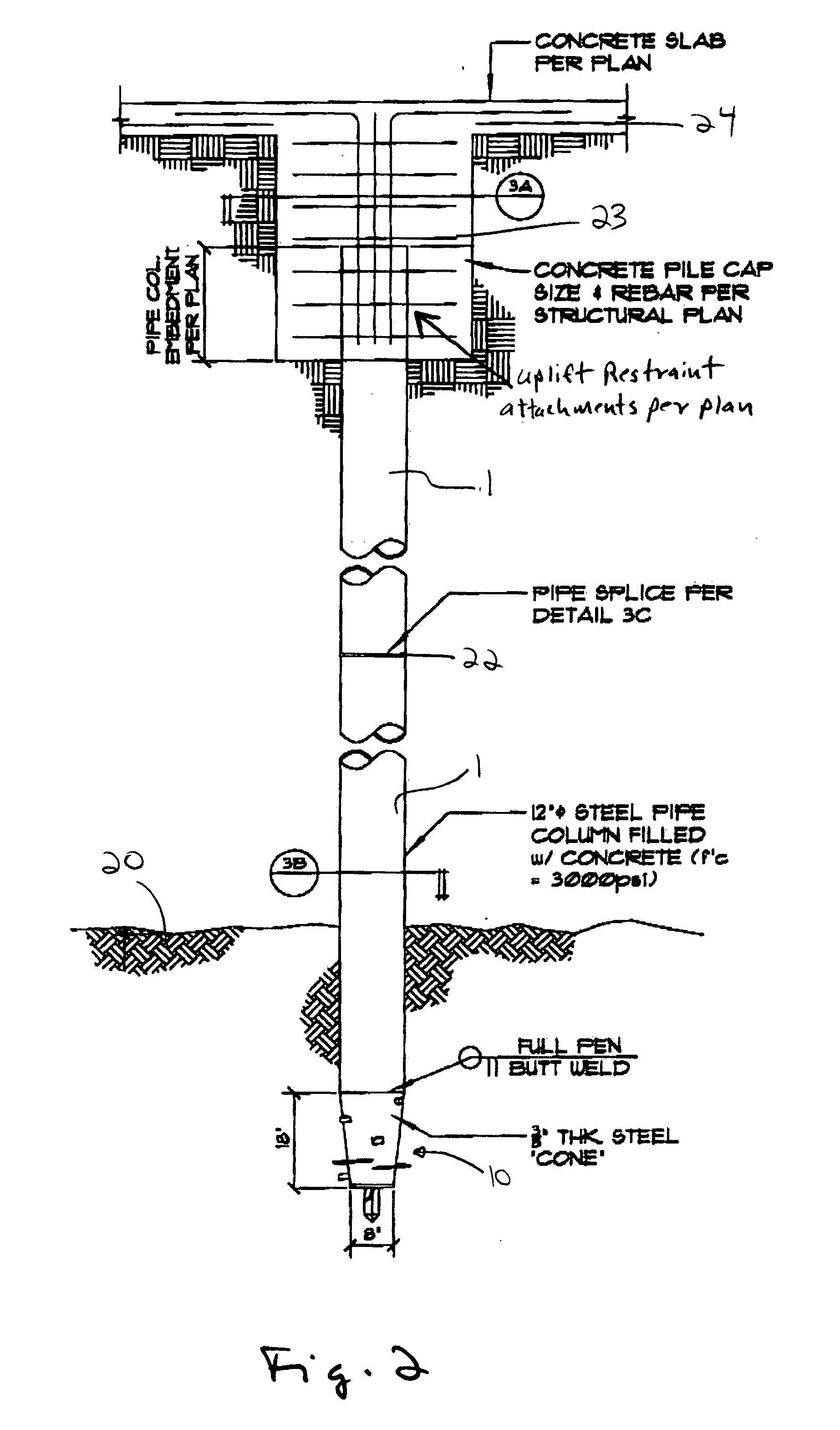
[0020] A method and apparatus is provided for the installation of a foundation pile in a soil bed. In contrast to prior art drilled foundation pile systems which use a low torque and an efficient drill tip which must be retrieved from the drilling site after drilling is complete, in an exemplary embodiment of the present invention a pile is provided with a fixed tip having a helical flight thereon which draws the pile into a soil bed when a torque is applied to the pile. FIG. 1 shows a conical pile tip 10 connected to a pile 1 according to one embodiment of the present invention, wherein the pile tip 10 allows the pile 1 to be set into a soil bed by applying a torque to the distal end of the pile 1 (not shown) using a standard drilling rig. The rig may additionally apply a crowd pressure to the pile 1 along with the torque to further aid in placement of the pile 1 in the soil bed to provide substructure support system for a large scale construction project.

[0021] In one embodiment,...


PUM


Abstract

A torque down pile substructure support system comprises a tubular pile with a fixed conical tip having a helical flight thereon which draws the pile into a soil bed when a torque is applied to the pile. The tip has a substantially conical shape, and the largest diameter of the tip is substantially the same as the diameter of the tubular pile to which it is attached. The helical flight is attached to the outside surface of the tip. The tip may also be provided a point tip and one or more cutting teeth attached its surface.

Description

CROSS-REFERENCE TO RELATED APPLICATION [0001] This application claims the benefit of U.S. Provisional Application No. 60 / 657,857, filed Mar. 2, 2005, the disclosure of which is incorporated fully herein.FIELD OF THE INVENTION [0002] The present invention relates to the installation of foundation piles in a soil bed, and particularly to a method and apparatus for the installation of a high capacity rotational substructure piling system. BACKGROUND OF THE INVENTION [0003] The installation of conventional foundation piles has previously been accomplished by driving a precast concrete pile or steel beam or vibrating an H pile into a soil bed. When driving a foundation pile, the soil surrounding the pile may be compacted in various ways as well as disrupted by the seismic shocks of the pile driver itself. When driving a pile into hard ground, earth displaced by the pile causes the ground surrounding the pile to heave. In contrast, when driving a pile into soft ground, settling of the sur...

Claims


Application Information

Patent Timeline
IPC IPC(8): E02D5/10
CPCE02D5/56E02D7/22
Inventor NEVILLE, STEVE
Owner DRILL TECH DRILLING & SHORING INC
Learn More