
Solid finite elements suitable for simulating large deformations and/or rotations of a structure

a technology of solid finite elements and structures, applied in the field of computer aided engineering analysis, can solve the problems of obscuring the purpose, requiring more computing resources, and complex computation, and achieve the effect of avoiding obscuring the purpos

Active Publication Date: 2011-11-01
ANSYS INC
View PDF1 Cites 2 Cited by
  • Summary
  • Abstract
  • Description
  • Claims
  • Application Information

AI Technical Summary

Problems solved by technology

As a result of the additional nodes, computation becomes more complex thereby requiring more computing resources.
This is a problem in today's production engineering environment as many of the modern FEA model comprises more than one million elements.
Another problem arises when the prior art solid elements are used in conjunction with shell elements in one FEA model.
The incompatibility at common nodes shared between solid and shell elements often created numerical problem that rendered the simulation results useless.

Method used


Image

  • Solid finite elements suitable for simulating large deformations and/or rotations of a structure
  • Solid finite elements suitable for simulating large deformations and/or rotations of a structure
  • Solid finite elements suitable for simulating large deformations and/or rotations of a structure

Examples


Embodiment Construction

[0025]In the following description, numerous specific details are set forth in order to provide a thorough understanding of the present invention. However, it will become obvious to those skilled in the art that the present invention may be practiced without these specific details. The descriptions and representations herein are the common means used by those experienced or skilled in the art to most effectively convey the substance of their work to others skilled in the art. In other instances, well-known methods, procedures, and components have not been described in detail to avoid unnecessarily obscuring aspects of the present invention.

[0026]Reference herein to “one embodiment” or “an embodiment” means that a particular feature, structure, or characteristic described in connection with the embodiment can be included in at least one embodiment of the invention. The appearances of the phrase “in one embodiment” in various places in the specification are not necessarily all referri...


PUM


Abstract

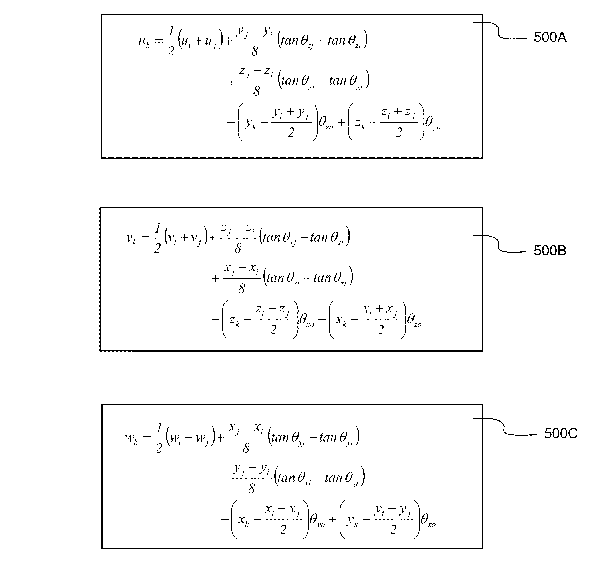
System and method of simulating large deformation and rotation of a structure in a finite element analysis used for improving structural design is disclosed. A solid finite element is configured for simulating large deformations and / or rotations of a structure. The solid finite element comprises only corner nodes with each node having six degrees-of-freedom (DOF), three translational and three rotational. In other words, each node is configured to include translational deformation and rotation deformation, each of the translational and rotational deformation has three components corresponding to one of the six DOFs. The solid finite element has a plurality of external edges. Each external edge has two ends, each end is located at one of the adjacent corner nodes. Additionally, translational deformation at mid-edge point of each external edge is implicitly embedded in the translational and rotational deformations of two adjacent corner nodes.

Description

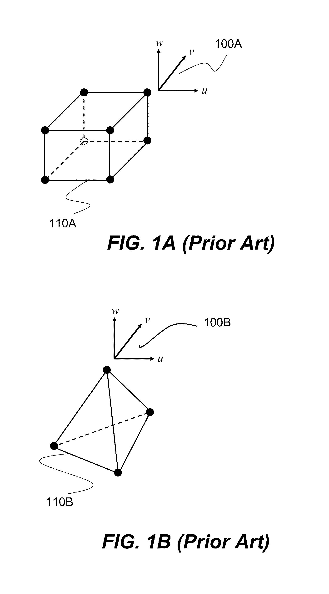
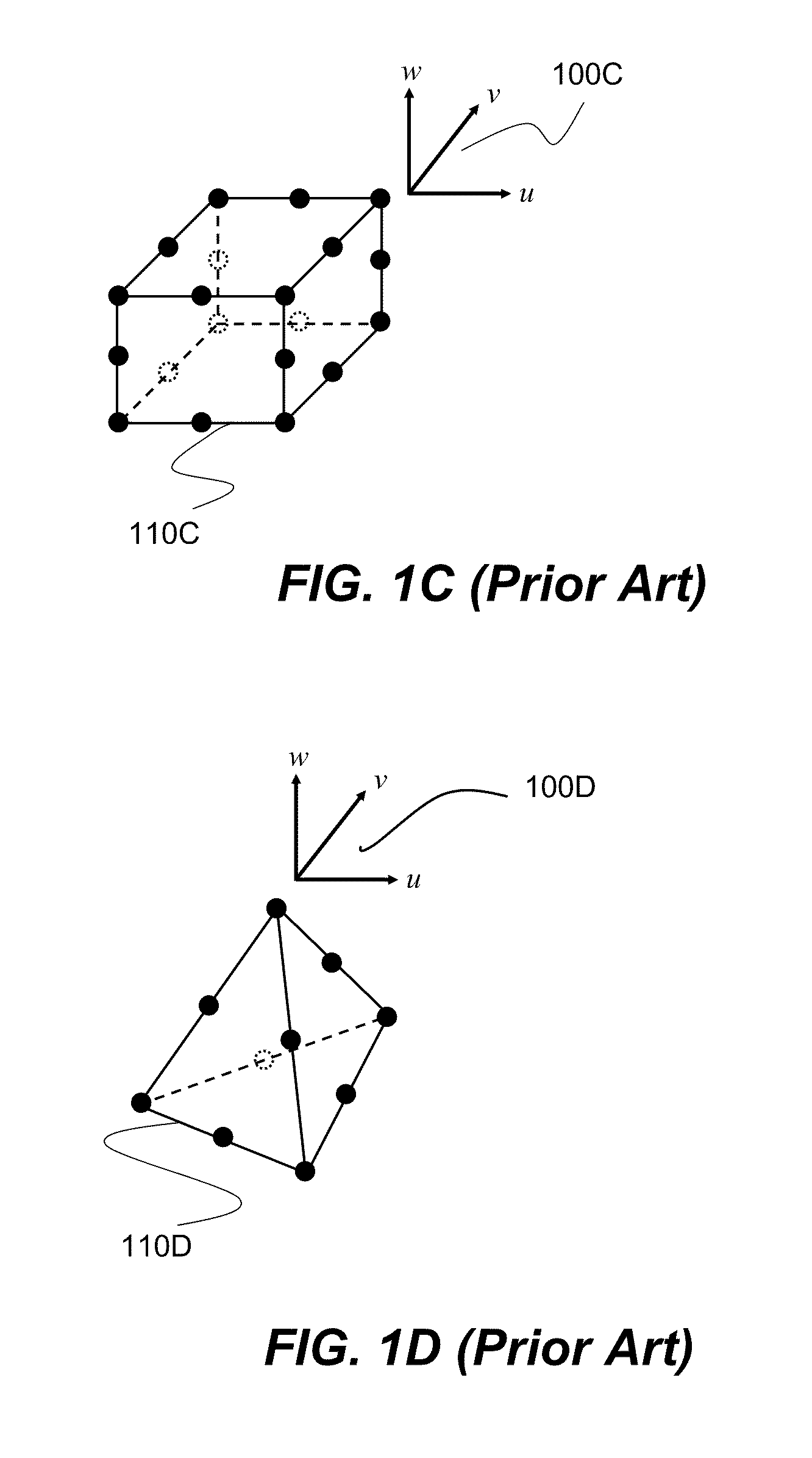
FIELD OF THE INVENTION[0001]The present invention relates to computer aided engineering analysis used for assisting engineers and scientists in making design decision of a structure (e.g., an automobile, an airplane, a consumer product, etc.), more particularly to systems and methods for providing improved special purpose solid finite elements suitable for simulating large deformations and / or rotations of a structure such as a turbofan of a turbojet engine.BACKGROUND OF THE INVENTION[0002]Finite element analysis (FEA) is a computer aided engineering tool that uses numerical methods to obtain approximate solutions to complex engineering systems. FEA is routinely used in many other engineering fields, especially structural designs. It is also widely used in simulating time-elapsed events, such as car crashing and metal forming. It is a very powerful tool and used extensively by engineers and scientists in evaluating new product designs and existing product refinements prior to actual ...

Claims


Application Information

Patent Timeline
Patent Type & Authority Patents(United States)
IPC IPC(8): G06F17/10
CPCG06F17/5018G06F30/23
Inventor TENG, HAILONGHALLQUIST, JOHN O.
Owner ANSYS INC
Learn More