A metal hose connection structure

A technology of metal hose and connection structure, which is applied in the direction of hose connection device, sealing surface connection, pipe/pipe joint/pipe fitting, etc. The hose body is broken and leaked, so as to avoid the failure to fix tightly, reduce the risk of rupture and leakage, and improve the service life.

Active Publication Date: 2019-03-12
WUHAN XINXIN SEMICON MFG CO LTD
View PDF7 Cites 0 Cited by
  • Summary
  • Abstract
  • Description
  • Claims
  • Application Information

AI Technical Summary

Problems solved by technology

[0003] At present, when the nut is rotated and locked to fix the metal hose body on the inlet and outlet manifolds, due to the rotational friction between the nut and the hose joint, the metal hose body will be driven to rotate along the nut Rotating in the direction of the metal hose, the frictional rotation of the metal hose that should not have will cause two effects; the first effect is that after the hose joint rotates, the metal hose body undergoes rotational deformation, and multiple such rotational deformations cause the metal hose The service life of the body is shortened, which also increases the risk of rupture and leakage of the metal hose body during use
The second situation is that the metal hose body will rebound after being deformed to a limit angle, causing the metal hose joints to be unable to be fixed tightly, and even gas leakage may occur; these are not expected by those skilled in the art of

Method used


Image

  • A metal hose connection structure
  • A metal hose connection structure
  • A metal hose connection structure

Examples


Embodiment 1

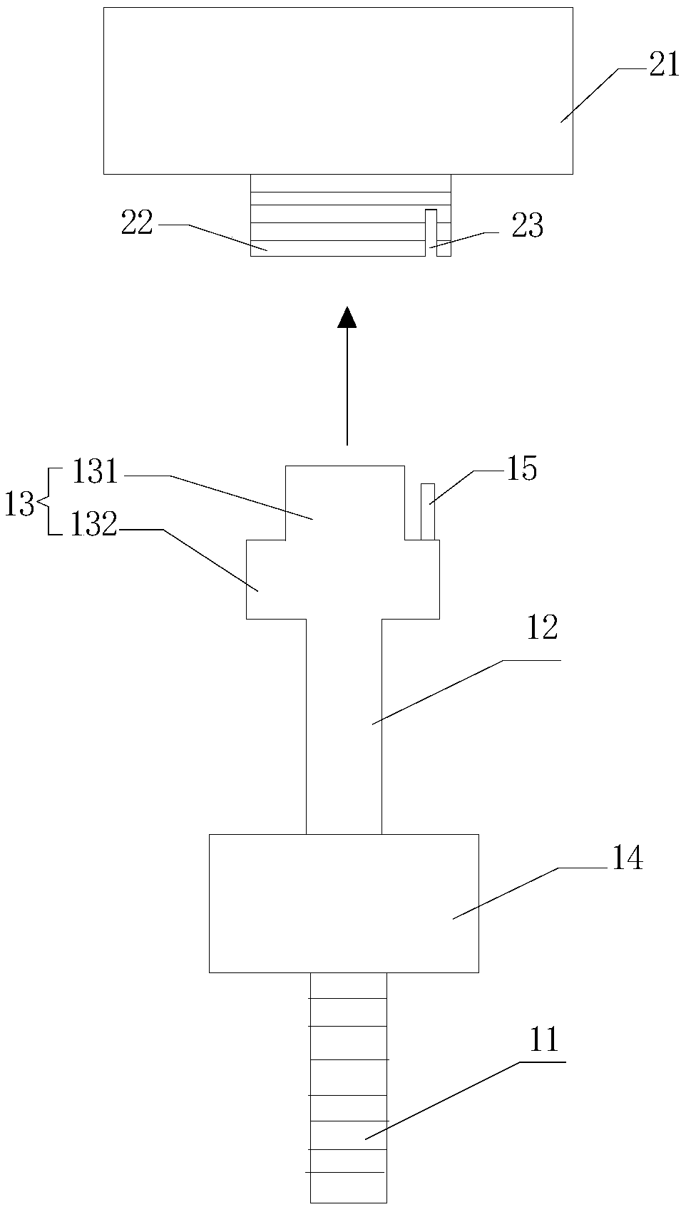
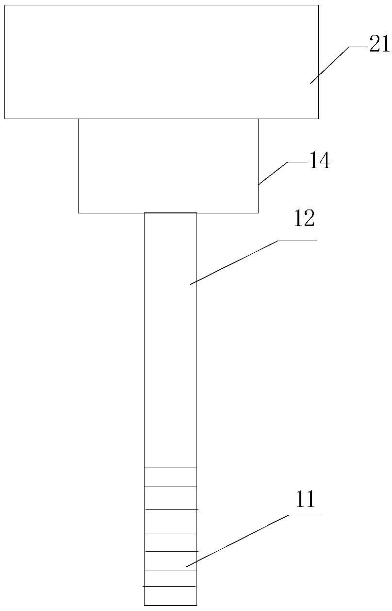
[0034] like Figure 1a and Figure 1b As shown, this embodiment relates to a metal hose connection structure, which can be applied to fix the metal hose body 11 on the inlet and outlet manifolds 21, and fix the hose connector 13 by setting the positioning pin 15 to eliminate the hose connector 13 Frictional movement due to the tightening nut 14 by rotation.

[0035] Specifically, the above-mentioned metal hose connection structure includes a manifold joint 22 and a metal straight pipe 12, the manifold joint 22 is arranged on the inlet and outlet manifold 21; one end of the metal straight pipe 12 is connected to the metal hose body 11, and the other end is provided with a The hose joint 13 that is compatible with the manifold joint 22 (the hose joint 13 is adapted to the manifold joint 22 is specifically: the upper part 131 of the hose joint 13 (that is, the part where the flange is not provided in the figure, the upper part and the lower part can be Referring to the position ...

Embodiment 2

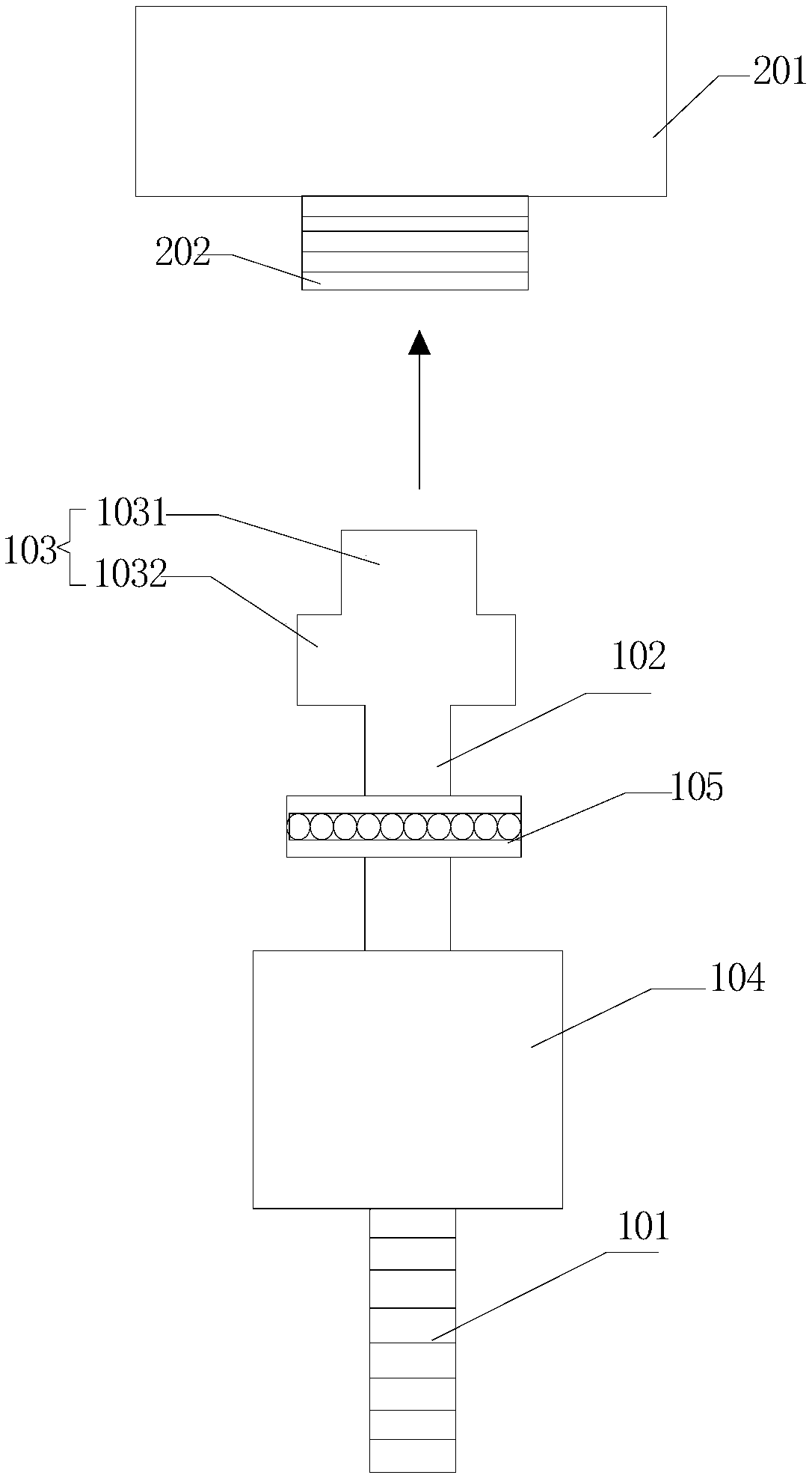
[0041] like Figure 2a and Figure 2b As shown, this embodiment relates to a metal hose connection structure, which can be applied to fix the metal hose body 101 on the inlet and outlet manifold 201 , and the frictional rotation can be minimized by setting the plane bearing 105 .

[0042] Specifically, the above-mentioned metal hose connection structure includes a manifold joint 202 and a metal straight pipe 102. The manifold joint 202 is arranged on the inlet and outlet manifold 201; one end of the metal straight pipe 102 is connected to the metal hose body 101, and the other end is provided with a The hose joint 103 that the manifold joint 202 is compatible with (the hose joint 103 is adapted to the manifold joint 202 is specifically: the outer diameter of the upper part 1031 of the hose joint 103 (that is, the part that is not provided with a flange) is approximately Smaller than the inner diameter of the manifold joint 202, and the length of the upper part 1031 of the hos...


PUM


Abstract

The present invention relates to the technical field of semiconductor equipment, in particular to a metal hose connection structure, which can be provided by setting a positioning pin on the hose joint of the metal hose structure, and setting the positioning pin on the manifold joint of the inlet and outlet manifold Matching gap; in the process of rotating the nut, the positioning pin can be used to limit the frictional movement of the hose joint in the direction of nut rotation, thereby eliminating the movement of the metal hose body in the direction of nut rotation; it can also be used A plane bearing is installed on the metal straight pipe of the metal hose structure, so that during the process of rotating the nut, the movement of the hose joint in the direction of nut rotation is reduced through the plane bearing, thereby reducing the movement of the metal hose body in the direction of rotation of the nut. The movement of the nut in the direction of rotation; this connection structure not only reduces the risk of metal hose rupture and leakage due to rotational deformation, improves the service life of the metal hose body, but also prevents the hose joint and manifold joint from being unable to be fixed tightly. The phenomenon.

Description

technical field [0001] The invention relates to the technical field of semiconductor equipment, in particular to a metal hose (gas bellow) connection structure. Background technique [0002] Because the metal hose has good flexibility, temperature resistance, pressure resistance and corrosion resistance, it is suitable for the transportation of steam, water, oil and various industrial gases, medicines and other media. The metal hose plays an important role in the movement of the piping system, thermal expansion absorption, and vibration absorption. In the semiconductor furnace tube machine, the process gas is also introduced into the reaction tube through the metal hose for reaction, and the metal hose is fixed on the inlet and outlet manifold (manifold) by tightening the thread. [0003] At present, when the nut is rotated and locked to fix the metal hose body on the inlet and outlet manifolds, due to the rotational friction between the nut and the hose joint, the metal ho...

Claims


Application Information

Patent Timeline
Patent Type & Authority Patents(China)
IPC IPC(8): F16L33/26F16L19/02
CPCF16L19/0206F16L19/0218F16L33/26
Inventor 周成志
Owner WUHAN XINXIN SEMICON MFG CO LTD
Why Eureka
Try Eureka