Tapered turning lathe

a turning lathe and tapered technology, applied in the direction of turning machines, portable lathes, manufacturing tools, etc., can solve the problems of inherently increasing the downtime of the machine being refurbished, and the lathe in the '093 patent is not readily configured to machine a tapered work pi

Active Publication Date: 2011-11-08
HYDRATIGHT OPERATIONS INC
View PDF7 Cites 22 Cited by
  • Summary
  • Abstract
  • Description
  • Claims
  • Application Information

AI Technical Summary

Problems solved by technology

This process of refurbishing the work piece inherently increased the downtime of the machine being refurbished.
The lathe in the '093 patent is not readily configured to machine a tapered work piece.

Method used


Image

  • Tapered turning lathe
  • Tapered turning lathe
  • Tapered turning lathe

Examples


Embodiment Construction

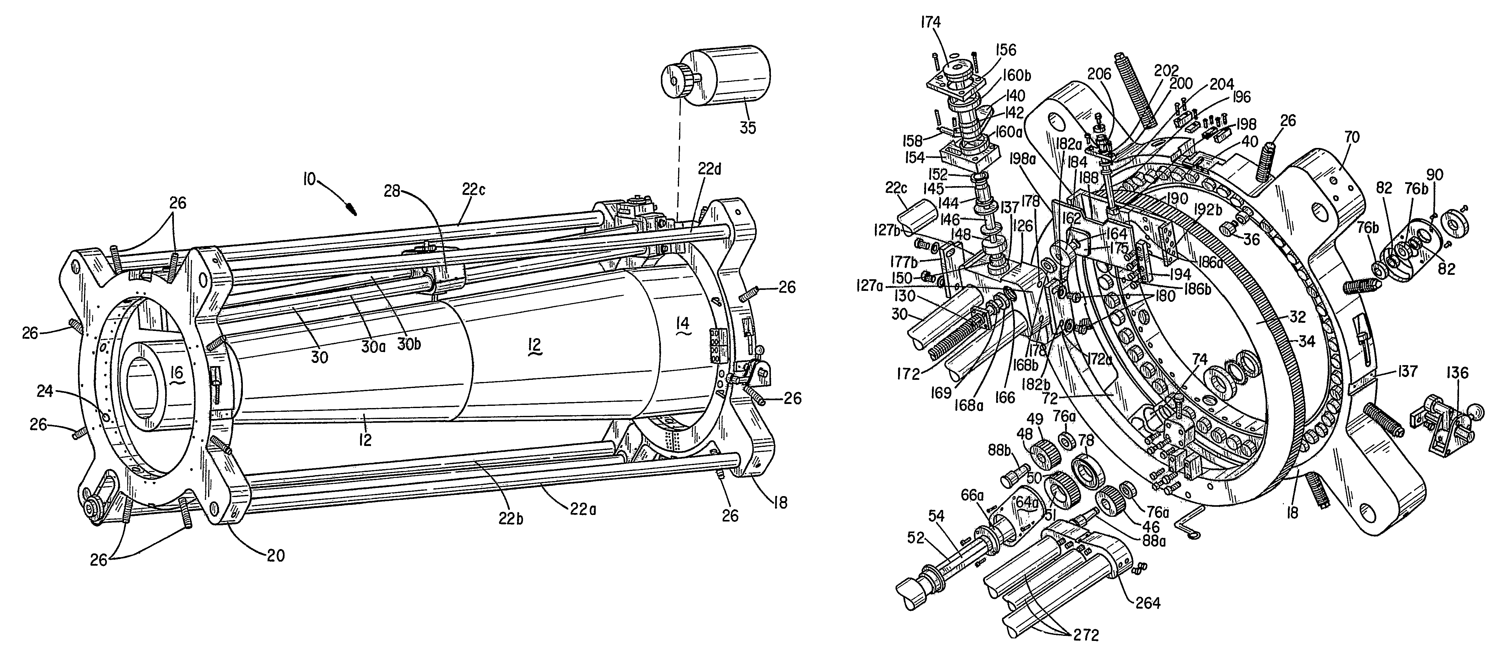
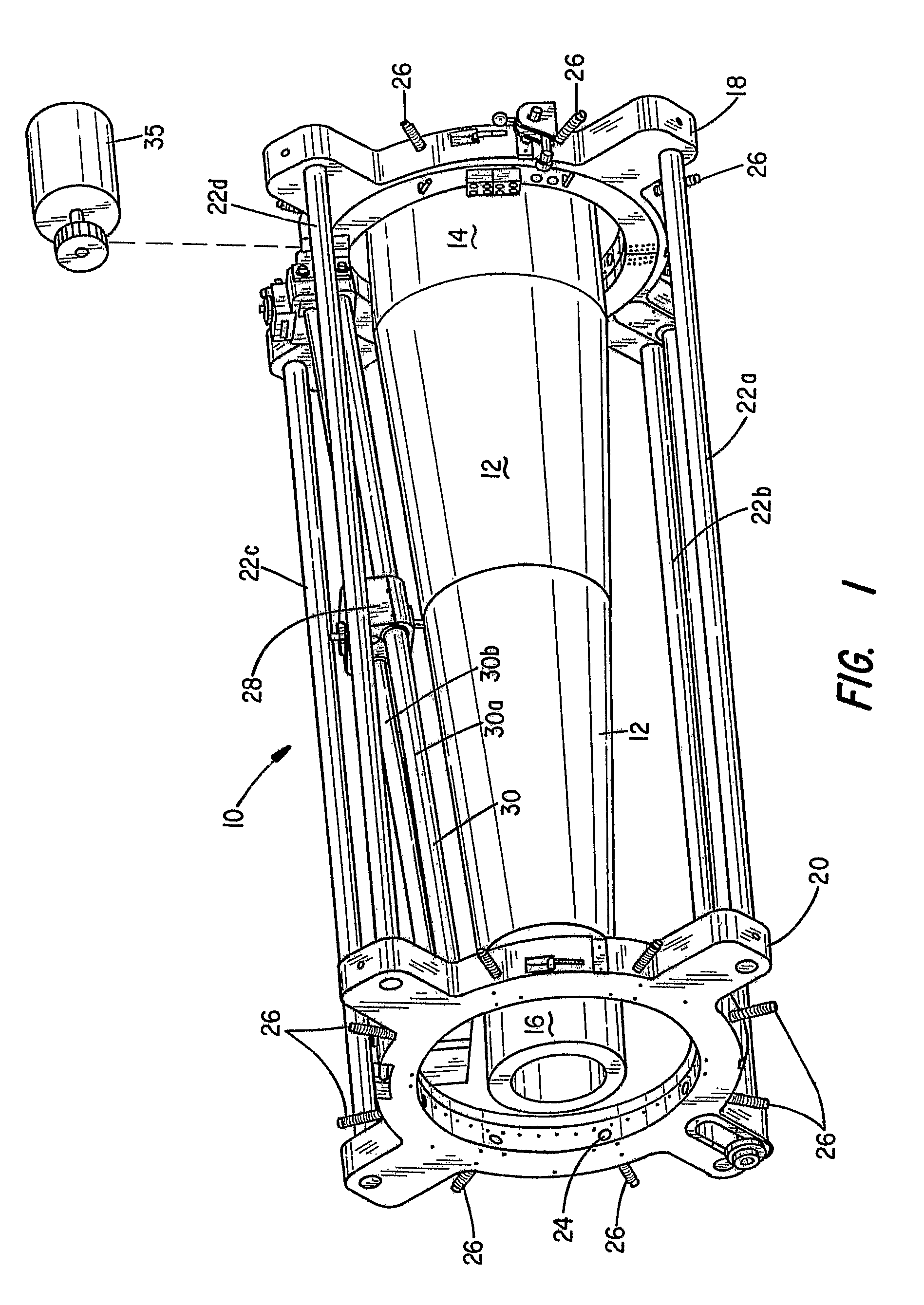
[0019]Referring first to FIG. 1, there is indicated generally by numeral 10 a tapered journal turning lathe constructed in accordance with the present invention. It is adapted to be mounted on a tapered work piece 12 having a first end 14 and a second end 16. Because the work piece 12 is tapered, the diameter of the work piece 12 gradually decreases from the first end 14 to the second end 16.

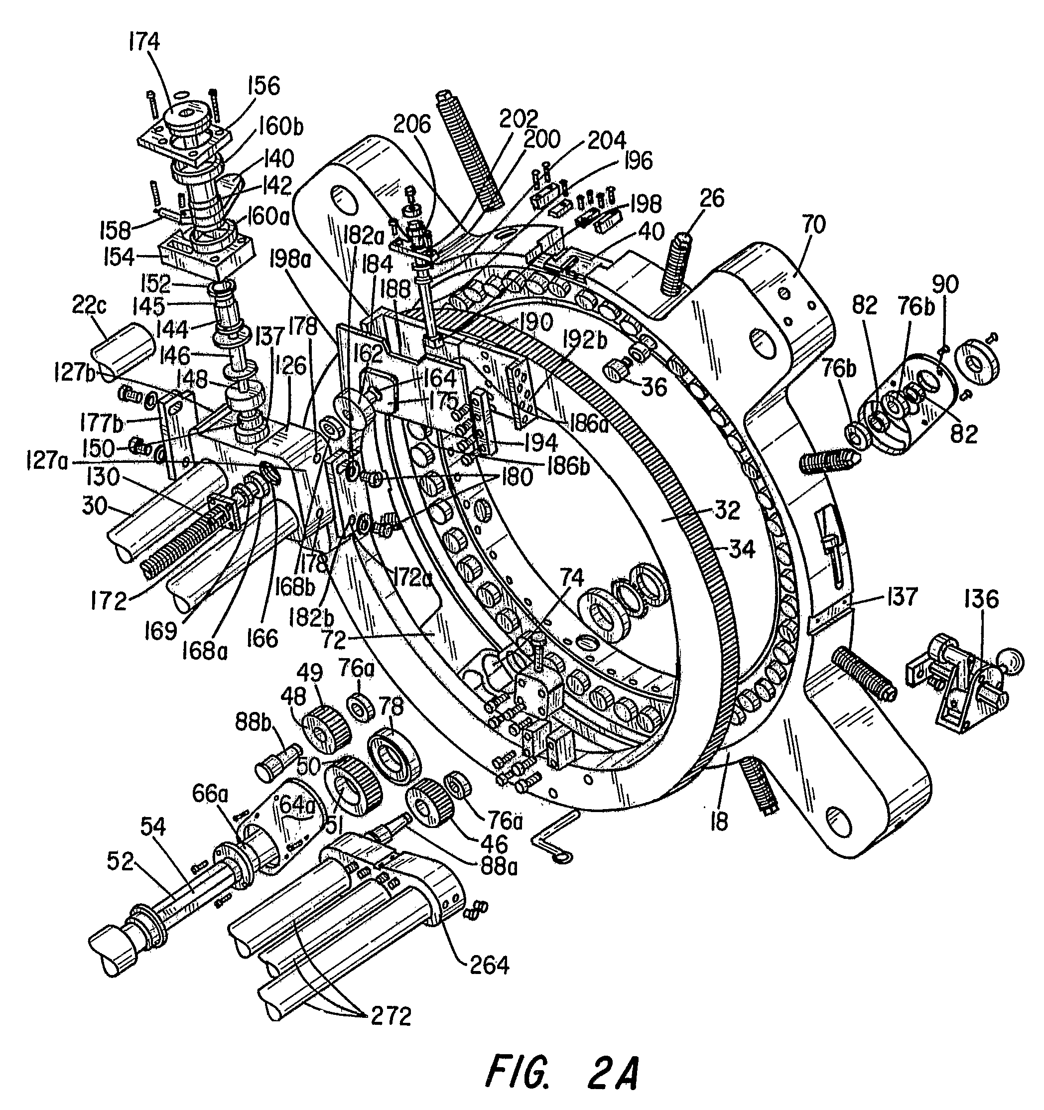
[0020]The journal turning lathe 10 is seen to comprise an annular drive housing 18 and an annular support housing 20 each having an inside diameter large enough to surround the tapered work piece 12 to be turned. The drive housing 18 and support housing 20 are connected by four support shafts 22a-22d. Formed radially through the thickness dimensions of both the drive housing 18 and the support housing 20 at intervals are equally radially spaced threaded bores, as at 24, into which there is threadily fitted a plurality of threaded locator screws 26 which are used to hold and center the lathe 10 t...


PUM

PropertyMeasurementUnit
angleaaaaaaaaaa
rotational movementaaaaaaaaaa
rotationaaaaaaaaaa

Abstract

A radially adjustable drive bracket (126) is affixed to, and rotatable with the drive gear (32), and a radially adjustable support bracket (128) is affixed to, and rotatable with the driven gear (42). A pair of parallel slide rails (30) are coupled at opposite ends to the drive bracket (126) and support bracket (128). A cutting head assembly (28) is slidably mounted on the slide rails (30), wherein a threaded lead screw (124) carrying a traveling nut (134) thereon causes longitudinal displacement of the cutting head assembly (28) along the slide rails (30). A cam arm (140) coupled through a one-way clutch to the lead screw (124) and adapted to be actuated by a tripper assembly (136) mounted so as to engage the cam arm (140) during orbiting movement of the drive and driven gear (32,42).

Description

FIELD OF THE INVENTION[0001]This invention relates generally to an apparatus for machining bearing surfaces of rotating shafts of large machines, and more particularly to a portable journal turning lathe that is adapted to repair and refurbish a tapered work piece and that can be readily transported to a worksite, assembled in place on the tapered work piece to be machined, and then operated to remove any scoring and other surface irregularities from the shaft so that it is ready for replacement of its bearings.DISCUSSION OF THE PRIOR ART[0002]It often becomes necessary to refurbish the journal area on a shaft of large machines such as rock crushers or ship rudders. In the past, as described in U.S. Pat. No. 5,660,093, it was necessary to tear down the machine and transport the shaft to a machine shop where it may be machined by an engine lathe weighing 90 tons or more. This process of refurbishing the work piece inherently increased the downtime of the machine being refurbished. Th...

Claims


Application Information

Patent Timeline
Patent Type & Authority Patents(United States)
IPC IPC(8): B23B5/16B23B41/00
CPCB23B5/38Y10T82/2527Y10T82/22Y10T82/25Y10T82/2522
Inventor RICCI, DONATO L.PLACE, BRENT
Owner HYDRATIGHT OPERATIONS INC
Why Eureka
Try Eureka