[0030]In order that the object of the invention may more readily be understood, the following description is given, merely by way of example, reference being made to the accompanying drawings.
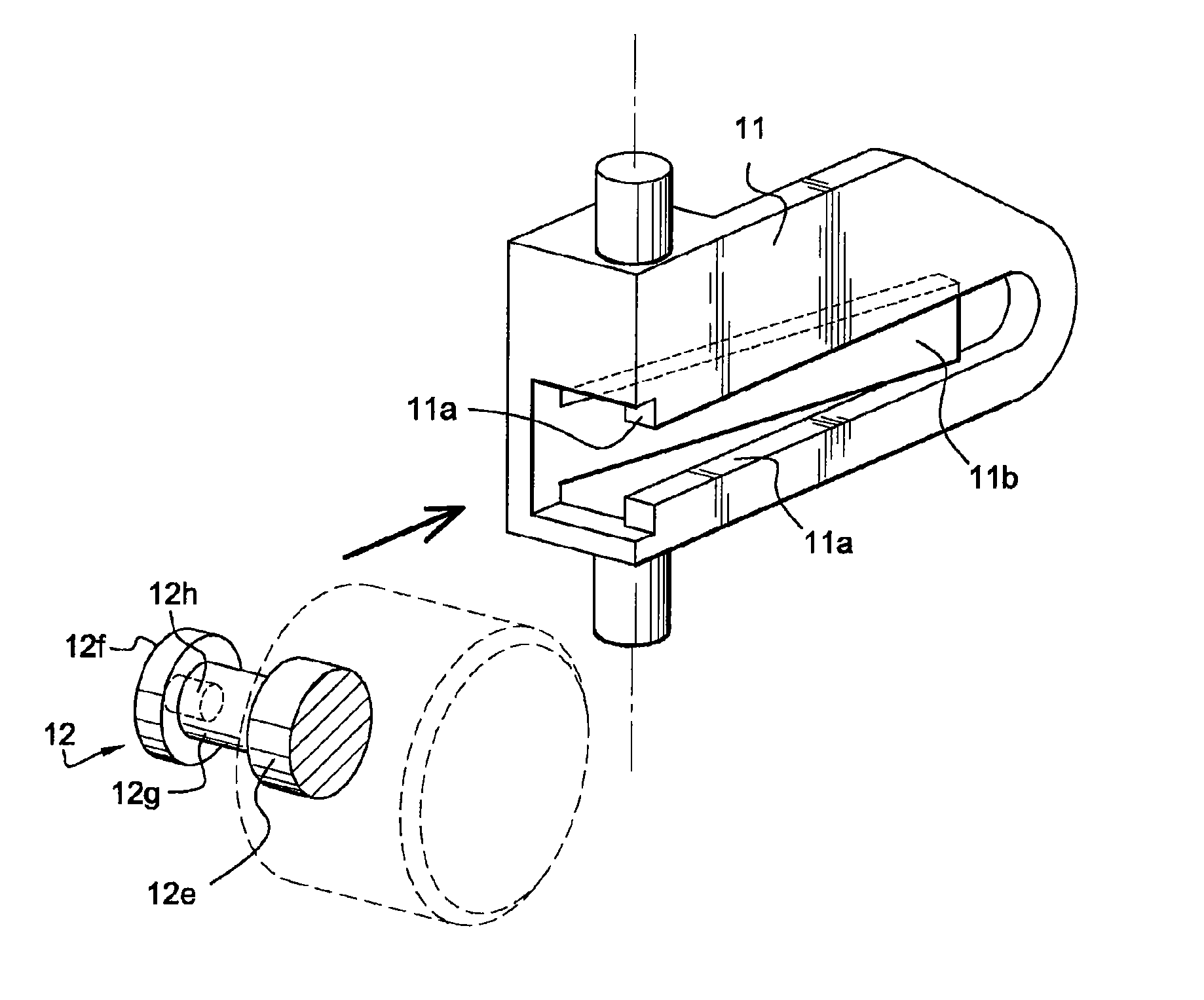
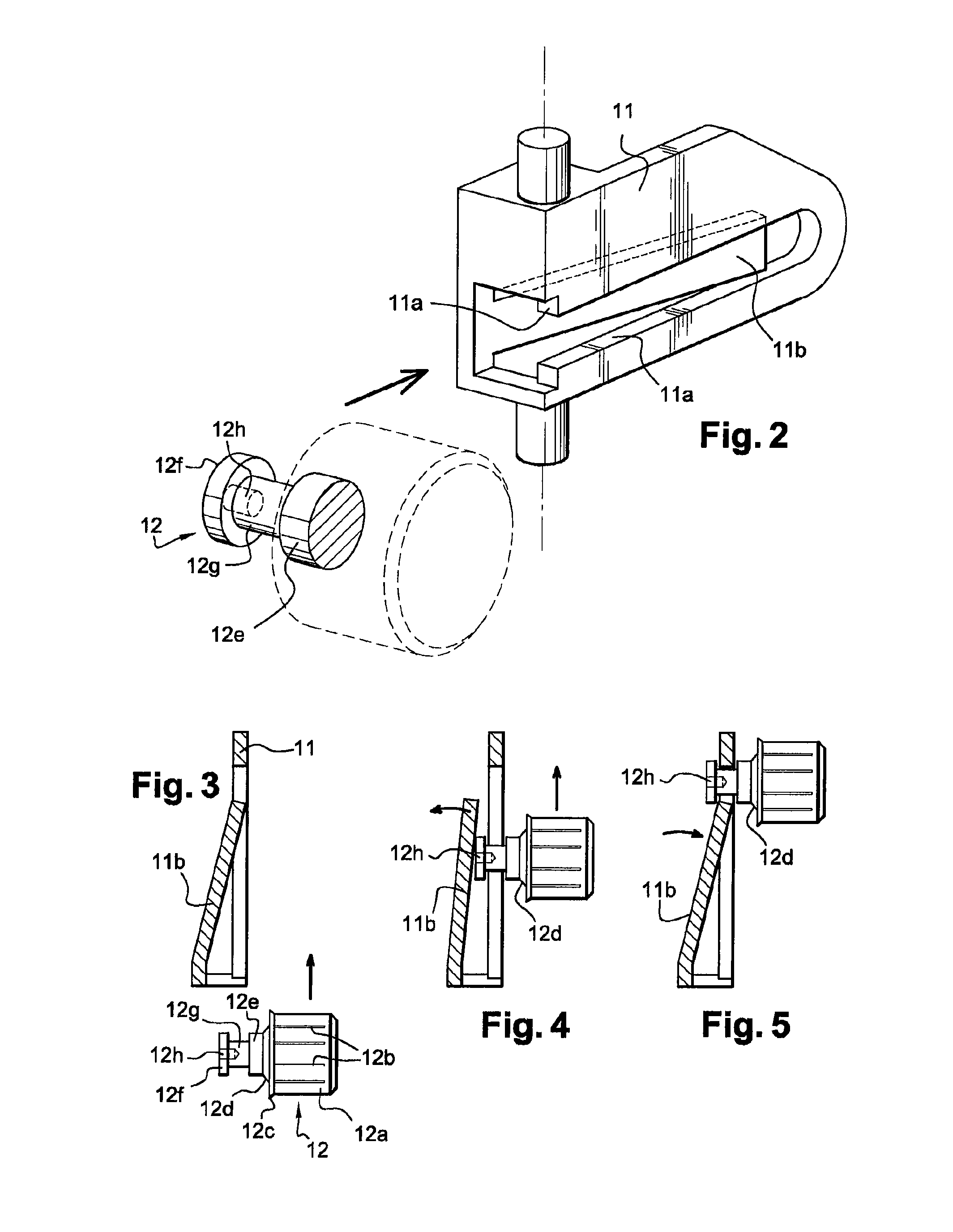
[0031]In FIGS. 6, 8 and 9, end piece (12) has a cylindrical bearing surface (12a) with splines (12b) and a transverse flange (12c) which fits tightly into the core. This area of the end piece which is intended to be located inside the core can be differently designed, the arrangement in the Figures merely being shown by way of example.
[0032]The front part of the end piece, i.e. that located outside the core, has beyond the transverse flange, an axial neck comprising a tapered bearing surface (12d) that extends as a cylindrical bearing surface (12e), a head (12f) at its end and, between these two, a hollowed-out section forming a groove (12g) to constitute a guide path. The presence or absence of the tapered part (12d) depends on the configuration of the end piece.
[0033]According to the invention, the head (12f) and the hollowed-out section (12g) forming the guide of end piece (10) are deformable and internally designed with a hole (12h) to create deliberate fragility, the function of which is to allow by subsequent crushing deformation of at least said head and, if applicable, the hollowed-out section when force is exerted to extract the core after closure of the roll. This deformation is made possible by the flexibility of the material of which the end piece is made and therefore the diameter and depth of the through-hole thus made.
[0034]The guide (11) illustrated in FIG. 2 or FIGS. 6, 7 and 9 is therefore designed with a slot into which the end piece is inserted with a protruding area that corresponds to the hollowed-out section (12g) of the end piece in order to guide it. It thus defines a constricted shape and the rear part of head (12f) of the end piece presses against the internal wall of said protruding area. In the normal situation shown in FIGS. 5 and 6 when there is material on the roll core, the end piece is perfectly retained with the hollowed-out part being centred around the protruding area of the guide. A tab (11b) capable of elastic deformation and joined to the guide maintains the end piece in position and prevents it escaping.
[0035]When the roll is completely exhausted, i.e. the core is empty (FIG. 8), the core must be extracted and removed. The core is swiveled in the direction of arrow (F1) and the upper part of the deformable head of the end piece pushes against the fixed protruding part of the guide. The tensile force exerted in the direction of arrow (F2) combined with the swiveling force causes crushing of at least the head of the end piece and, if applicable, also the hollowed-out part. Hole (12h) allows the walls of the head of the end piece to move towards each other, thereby allowing clearance by clamping the head in the constriction or opening formed on the bottom between its protruding parts (FIG. 9). Due to the nature of the material of which the end piece and its front part are made, head (12h) is then irreversibly deformed with, for instance, a regular or irregular oval configuration as shown in FIG. 10, depending on the force and tensile forces exerted.
[0036]The end piece of the core can no longer be used because of deformation of its front part and this solves the problem in question. The deformation of the head of the end piece and hence its hollowed-out section thus obtained does not create any risk of cracking or breakage of the head from the body of the end piece and there are therefore no loose fragments that can remain inside the dispensing apparatus.
[0037]Without going beyond the scope of the invention, the front surface of the head of the end piece has partial cuts in its thickness in the form of a cross (12m) in order to facilitate bending and deformation of the head of the end piece in order to make it deliberately more fragile.
[0038]It is now time to describe the end piece variant, shown in FIG. 12, which is designed with a deformable head in order to fulfil the deformation function which involves its destruction, as referred to above, as well as another function of locking in an articulated flap associated with a support side piece of the roll of material in the dispensing apparatus.
[0039]In FIG. 12, the reference numbers used for the deformable end piece are the same, apart from the fact that hollowed-out section (12g) has a very particular configuration. It actually has two opposite-facing curved restrictions (12g1) which reduce the thickness of section (d1) to roughly 1.5, to 2, mm, whereas section (d2) in the plane which is perpendicular to it has a section which is approximately 3, to 4, mm thick. Besides facilitating deformation of the head of the end piece, this arrangement has a specific advantage when it comes to locking the end piece.
[0040]In contrast to using the locking tab (11b) shown in FIGS. 2, 3, 4 and 5, the end piece with a deformable head can be used with a device which is shown in FIGS. 14, 15 and 16. The inside part of one of the side pieces (13) which receives the roll-holder core is designed with a seat-shaped part (13a) delimited by an outline which matches the shape of a flap-shaped support (14) which has cradles (13f) that accommodate the hinge pins (14a) of said flap. Inside the space defined by the seat, there is a partially emerging slot (13c) which is substantially horizontal from front to back and provides a gap through which the end piece can pass. Flap-shaped support (14) has a guide path (14b) defined by an oblong slot (14c) in its thickness with longitudinal fins (14d) which form guide rails. The rear surface (14e) has a recess (14f) forming a seat for spring (15) which rests against the opposite-facing surface of the side piece.
[0041]The special configuration of the end piece, shown in FIGS. 12 and 13, enables cooperation with the above-mentioned device, especially a maximum constriction equal to a distance between the guide fins of 1.5, to 2, cm, so that it is only possible to insert section (d1) of the end piece in one direction, given the fact that its section (d2) in one plane differs from that (d2) in the other plane. Indeed, raised or other types of guide marks (12i) can be provided on the end piece to show the direction in which it is inserted into the flap-shaped support. In addition and according to a specific feature of the above-mentioned support, the end of oblong slot (14e) has a round recess (14g) which matches the profile of the head of the end piece.
[0042]As shown in FIGS. 15 and 16, when the end piece is fitted in the articulated flap-shaped support, spring (15) is compressed and the support is in contact with the receiving support side piece. When it reaches the end of its travel, the head of the end piece fits into round recess (14g) and the end piece is locked due to expansion of the spring.
[0043]The end piece, together with the core of the roll, is removed under the conditions described above and doing so damages it by deforming the head.
[0044]This alternative embodiment of the end piece offers a specific advantage thanks to the differentiated section of hollowed-out area (12g) which is intended, by specifically designing the flap-shaped support, to prevent any use of competitors' end pieces which are thus incapable of being inserted into the above-mentioned support because of their inappropriate configuration and section.
[0045]The solution provided by the Applicant appears simple to implement but choosing this solution is not at all obvious, given the original problem to be solved. There are many manufacturers of apparatus for dispensing wiping material throughout the world and considerable quantities of several hundred million rolls of wiping material are used every year.