
Multi-tether cross-wind kite power

a cross-wind kite and multi-tether technology, applied in the direction of electric generator control, machines/engines, transportation and packaging, etc., can solve the problems of reducing the economic utility potential of all kite power extraction methods, weight, drag, cost, etc., to reduce the risk of electrical conductors and airborne generating equipment, and reducing the economic utility potential.

Active Publication Date: 2011-11-29
TIGNER BENJAMIN
View PDF9 Cites 28 Cited by
  • Summary
  • Abstract
  • Description
  • Claims
  • Application Information

AI Technical Summary

Benefits of technology

[0028]In some instances it may be advantageous to fly a given kite using three or more tethers. An airborne joint can be used ...

Problems solved by technology

All kite power extraction methods suffer severe performance penalties associated with the weight and drag of the tether.
This method is incapable of sustaining continuous power generation because of the need to rewind the tether, but the power required to rewind the tether can be a small fraction of the power generated during tether unwind.
Though the drag power extraction method offers the possibility of continuous power generation, the weight, drag, cost, and risk of the electrical conductors and airborne generating equipment reduce the potential for economic utility.
Both methods introduce considerable logistical complexity in the control and management of the kites and their tethers.
Each of these methods also pays a large performance penalty because neither method is conducive to the high-speed crosswind maneuver patterns that allow the most efficient energy extraction.
Many of the proposed systems present logistical challenges for launch and recovery of the kites, especially in cases where the kites are too large to be hand-launched by human operators.

Method used


Image

  • Multi-tether cross-wind kite power
  • Multi-tether cross-wind kite power
  • Multi-tether cross-wind kite power

Examples


Embodiment Construction

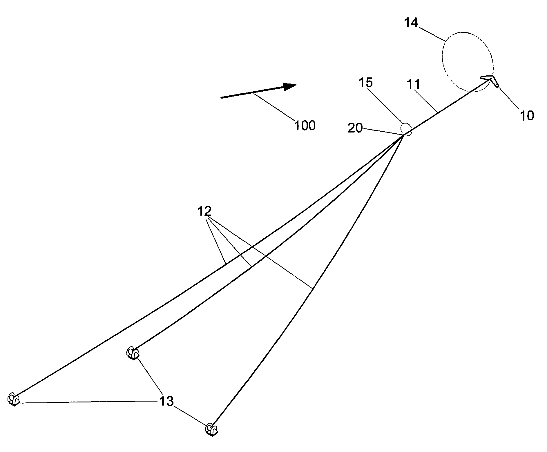
[0037]In FIG. 3, which shows a three-tether preferred embodiment, a kite 10 is attached to a secondary tether 11. The lower end of the secondary tether is attached by a joint 20 to the upper ends of each of two or more primary tethers 12, each of which is attached at its lower end to a ground-based spool 13. The ground-based spools are distributed on the ground, separated from each other by a distance. The kite flies a high-speed maneuvering pattern 14 approximately cross-ways to the wind, whose direction is indicated by the arrow 100, causing the lower end of the secondary tether to travel along a similar but smaller path 15. Since the distance between the kite and each ground-based spool changes in periodic way based on the geometry of the kite's orbit, each of the tethers must unwind and rewind on its spool in a periodic fashion. The ground-based spools are controlled in such a way that each tether unwinds under high tension and rewinds under low tension. The power generated whil...


PUM


Abstract

A multiple-tethered kite extracts power from wind. Systems having three or more tethers coupled to a single kite are contemplated, as are systems having multiple kites coupled to a given pair of tethers. Commercially useful tethers would most likely have a length of at least 1000 meters, and would be fixed at least 100 meters apart. During a given cycle the distance between each of the bases and the kite would likely vary by at least 50 meters. Motion of the tethers can be converted to useful energy in any commercially viable manner, for example by driving an electric generator or a water pump.

Description

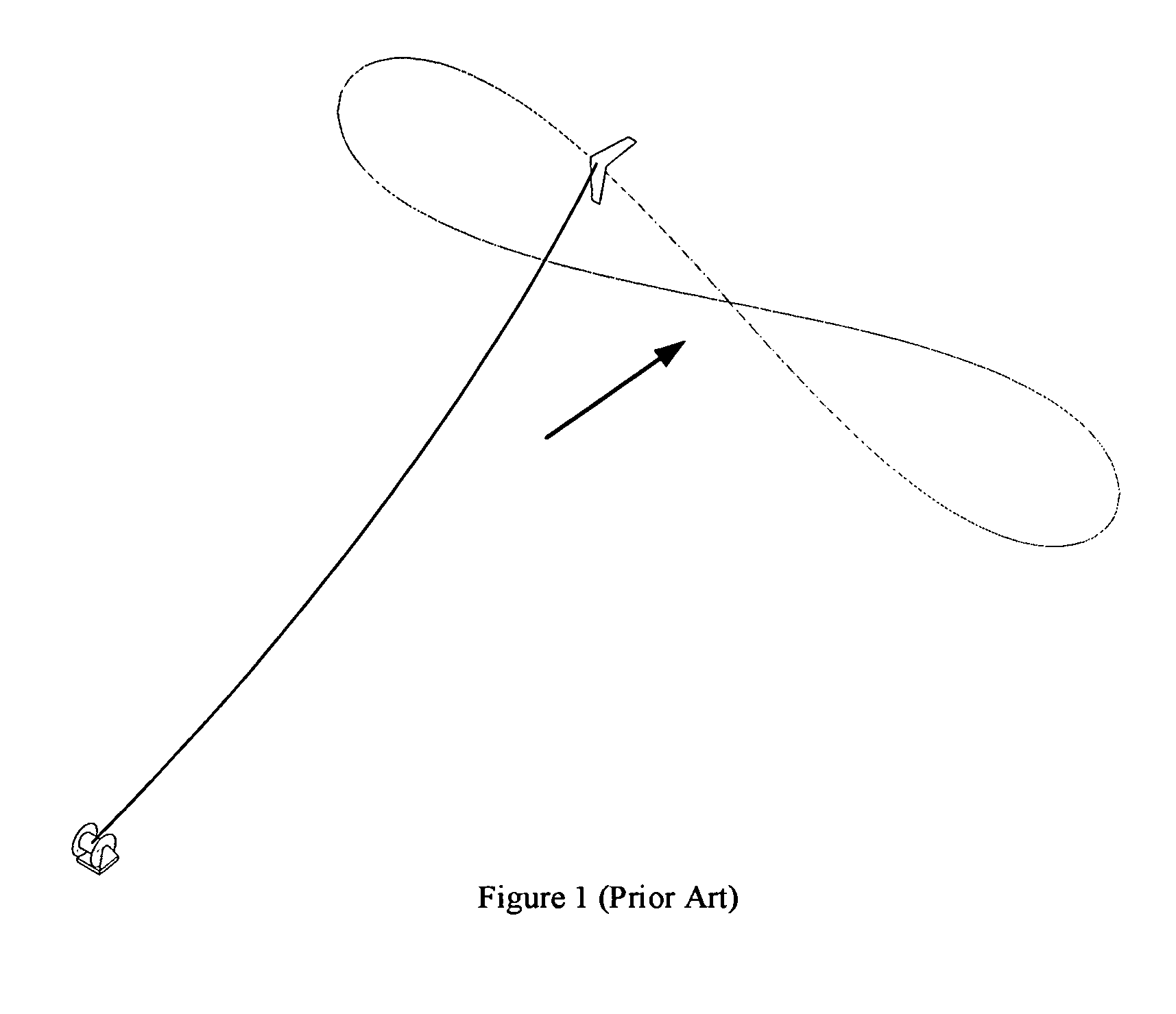
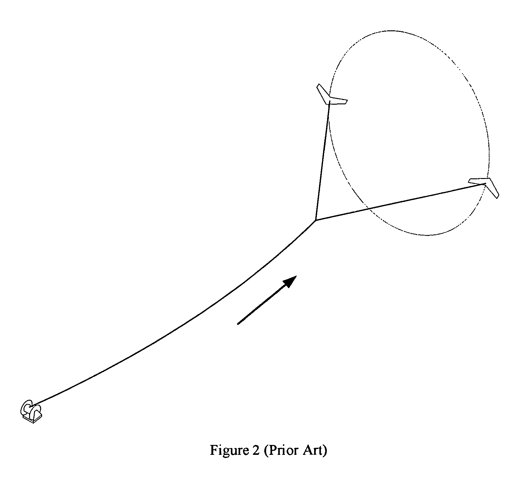
PRIORITY[0001]This application claims priority to U.S. provisional application Ser. No. 61 / 024,969 filed Jan. 31, 2008. That application, and all other extrinsic references identified herein are incorporated by reference in their entirety. Where a definition or use of a term in an incorporated reference is inconsistent or contrary to the definition of that term provided herein, the definition of that term provided herein applies and the definition of that term in the reference does not apply.FIELD OF THE INVENTION[0002]The field of the invention is power extraction from high altitude wind using kites.BACKGROUND[0003]Kites have been used for centuries for a variety of purposes associated with art, sport, and military reconnaissance. As used herein, the term “kite” broadly includes any object that is tethered, and remains in the air under power of the wind. This includes, for example, common play kites, a tethered blimp (also known as an aerostat), and a tethered toy or other airplane...

Claims


Application Information

Patent Timeline
IPC IPC(8): B64C31/06
CPCF03D5/00Y02E10/70
Inventor TIGNER, BENJAMIN
Owner TIGNER BENJAMIN
Learn More