
Putter head

a technology of putter head and putter head, which is applied in the field of putter head, can solve the problems of affecting the rolling of golf balls, and achieve the effect of smooth rolling

Inactive Publication Date: 2011-11-29
BRIDGESTONE SPORTS
View PDF26 Cites 15 Cited by
  • Summary
  • Abstract
  • Description
  • Claims
  • Application Information

AI Technical Summary

Benefits of technology

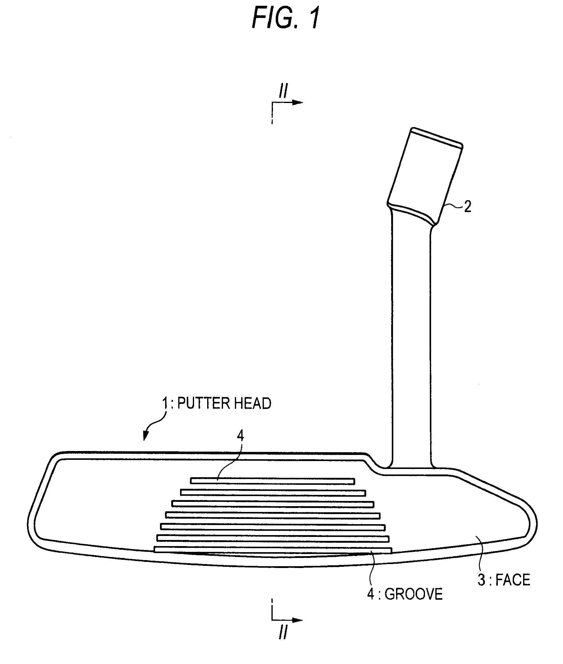
[0006]A putter head generally has a loft angle of from 2 to 5°, and a photographing with a high-speed camera reveals that the gold ball is given a backspin immediately after the impact. Such backspin hinders the rolling of the golf ball. An object of the present invention is to provide a putter head so improved as to reduce the backspin.
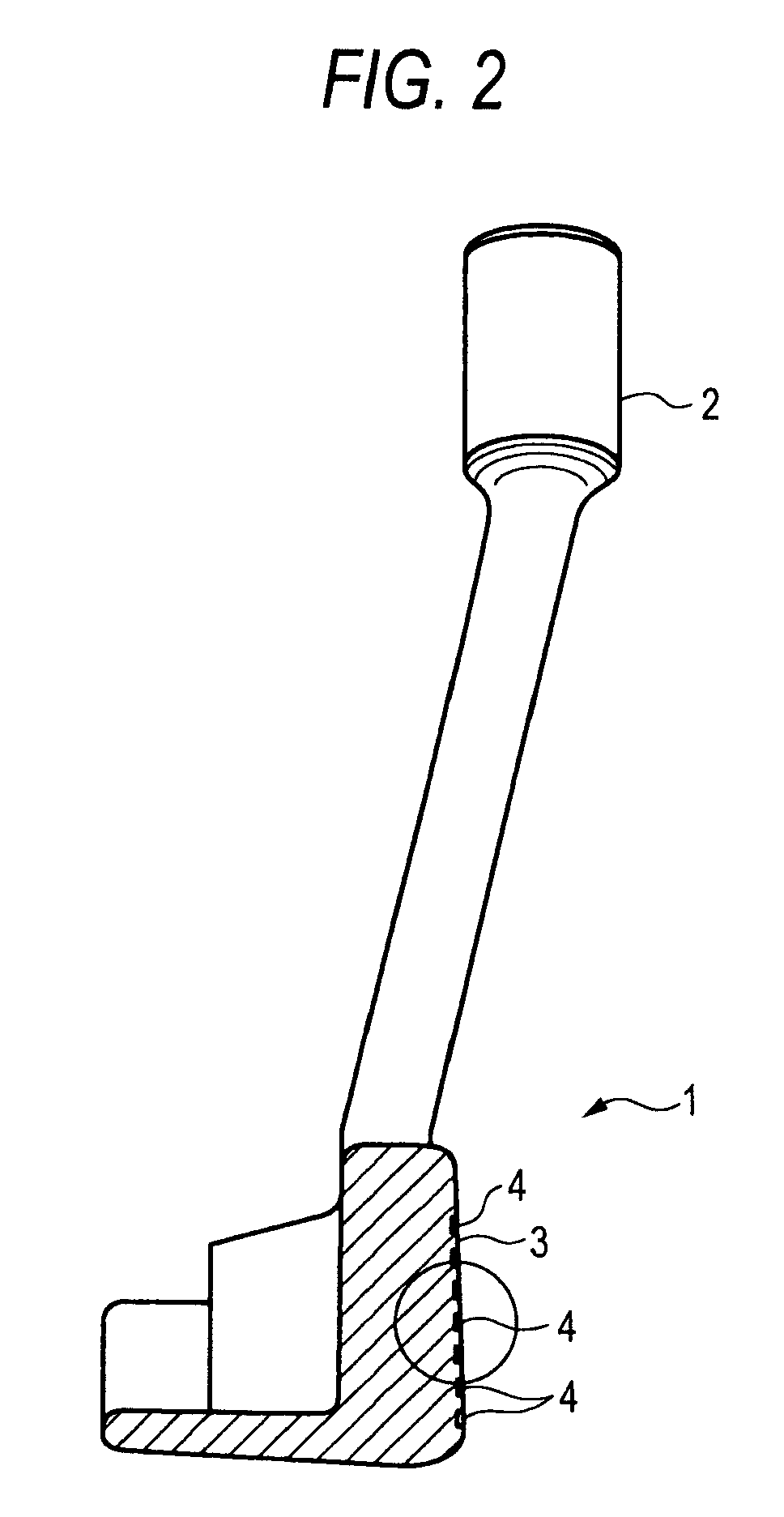
[0014]As a result of investigations undertaken by the present inventors, it is found that the backspin could be reduced by decreasing a contact area between the face and the ball. Also a hit mark, left on the face of the putter after hitting the ball, investigated by applying a pressure-sensitive marking sheet on the face, is found as a mark having a diameter of 3 to 5 mm, indicating that the ball is deformed to a certain extent.
[0017]In the putter head of the present invention, as the putted bail has a low backspin amount as described above, the ball starts a forward spin in an earlier stage after leaving the face, and smoothly rolls on an aimed line. It is also possible to prevent a phenomenon, particularly when the grass leaves on the green are grown inversely, that the rolling distance does not stretch unexpectedly and remains excessively too short (leaving a long distance from the stopped ball to the hole). In the present invention, the feeling of hitting may be regulated by constituting the face with an insert member of a material different from that of the main body of the putter head.

Problems solved by technology

Such backspin hinders the rolling of the golf ball.

Method used


Image

  • Putter head
  • Putter head
  • Putter head

Examples


example 6

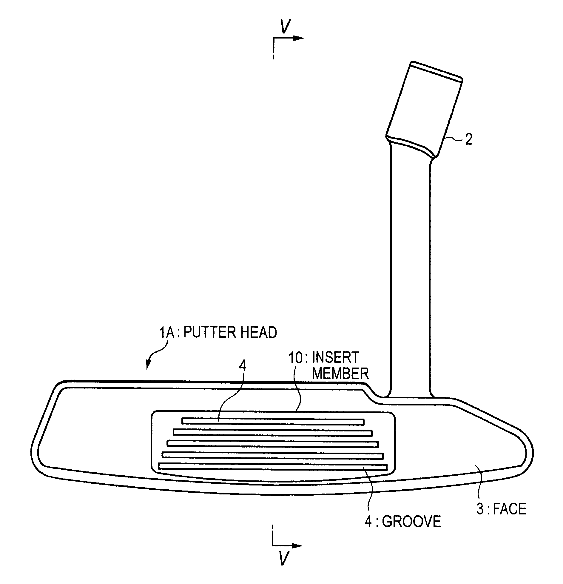
[0064]Samples of putter head 1A as illustrated in FIGS. 4 to 7 are prepared with the first insert members 10 and the second insert members 20, and used by golfers for testing, and the feeling of hitting is gathered. In the samples Nos. 1 and 2, the second insert member 20 is dispensed with and the first insert member 10 alone is used.

[0065]The dimensions of the first insert member 10 were as follows:[0066]length in toe-heel direction: 60 mm[0067]height: 14 mm[0068]thickness T: 4 mm[0069]thickness N of peripheral wall: 1.5 mm[0070]depth of concave 11: 2 mm[0071]Combinations of the materials of the insert members are as follows. In the samples Nos. 3 to 8, the left side of a symbol “+” indicates the material of the first insert member, and the right side indicates the material of the second insert member:[0072]No. 1 first insert member 10 of stainless steel only[0073]No. 2: first insert member 10 of aluminum alloy only[0074]No. 3: stainless steel+high hardness resin[0075]No. 4; alumin...


PUM


Abstract

A putter head includes substantially parallel plural grooves formed on a face thereof, wherein a ratio W / S of a groove width W (mm) and a space width S (mm) between the grooves is from 0.5 to 2.0.

Description

BACKGROUND OF THE INVENTION[0001]1. Field of the Invention[0002]The present invention relates to a putter head for golfing, and more particularly to a putter head having grooves on a face thereof.[0003]2. Description of the Related Art[0004]A putter head is a head part of a putter, which is a golf club for rolling a ball on a green. According to JP-A-2003-777, often found is a face having grooves, formed by a cutting work with a milling machine and called a milled pattern, over the entire surface of the face in an equidistant arc-shaped pattern when seen from a front side of the face. Such grooves are provided for various advantages such as for obtaining a soft feeling owing to a reduced contact area with the golf ball, avoiding a ball slippage in a state where the face is wetted with rain or dew, and providing a good appearance by a designed pattern, and are often found in putter club head for an advanced player, giving emphasis on feeling of hitting and of use.[0005]JP-A-2003-777 ...

Claims


Application Information

Patent Timeline
Patent Type & Authority Patents(United States)
IPC IPC(8): A63B53/04
CPCA63B53/04A63B2053/0416A63B2053/042A63B2209/00A63B2053/0408A63B2053/0445A63B53/042A63B53/0408A63B53/0416A63B53/0445A63B53/0487A63B60/46
Inventor TATENO, ATSUOISHIKAWA, TATSUYABAN, WATARUSATO, FUMIAKI
Owner BRIDGESTONE SPORTS
Learn More