Putter-heads

a head and putter technology, applied in the field of putterheads, can solve the problems of reducing the ability of the head to rotate about the principal heel-toe axis at impact, reducing the ability of the head to rotate about the heel-toe axis significantly, and reducing the backspin. , to achieve the effect of significant effect on the putting characteristics of the head, reducing backspin, and reducing the variation in putt length as a function o

Inactive Publication Date: 2006-02-09
LINDSAY LTD
View PDF19 Cites 7 Cited by
  • Summary
  • Abstract
  • Description
  • Claims
  • Application Information

AI Technical Summary

Benefits of technology

[0006] The combination of a compliant shaft coupling arrangement and a variable loft impact face in a putter according to the invention has been found to endow it with advantageous characteristics that are not achieved with known forms of putter. In particular, the de-coupling of the shaft stiffness at impact significantly reduces the effective height of the horizontal rotation axis parallel to the impact face (the principal heel-toe axis) and the effective moment of inertia about this axis and, combined with variable putter face loft, generally reduces backspin, provides a mechanism whereby variations in putt length as a function of impact height are reduced and allows implementations where backspin is eliminated over the useful part of the impact face.

Problems solved by technology

With this head function G=575, which provides moderate dS / dh, but the high hc combined with positive loft results in backspin increasing significantly with low impact-height and this in turn results in (the predicted) loss of distance at low impact height.
In this respect, neck extensions normally form a rigid part of the putter-head structure and so drastically reduce the ability of the head to rotate about its principal heel-toe axis at impact.

Method used


Image

  • Putter-heads
  • Putter-heads
  • Putter-heads

Examples


Embodiment Construction

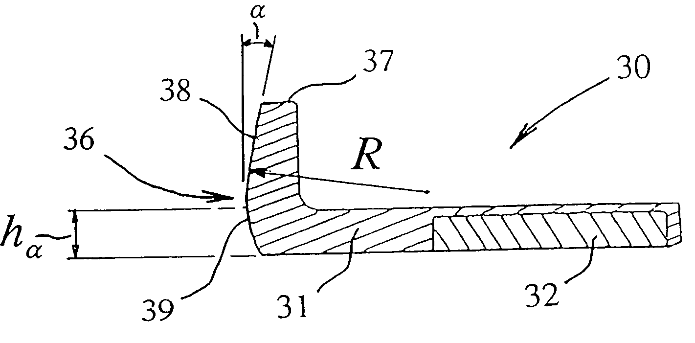
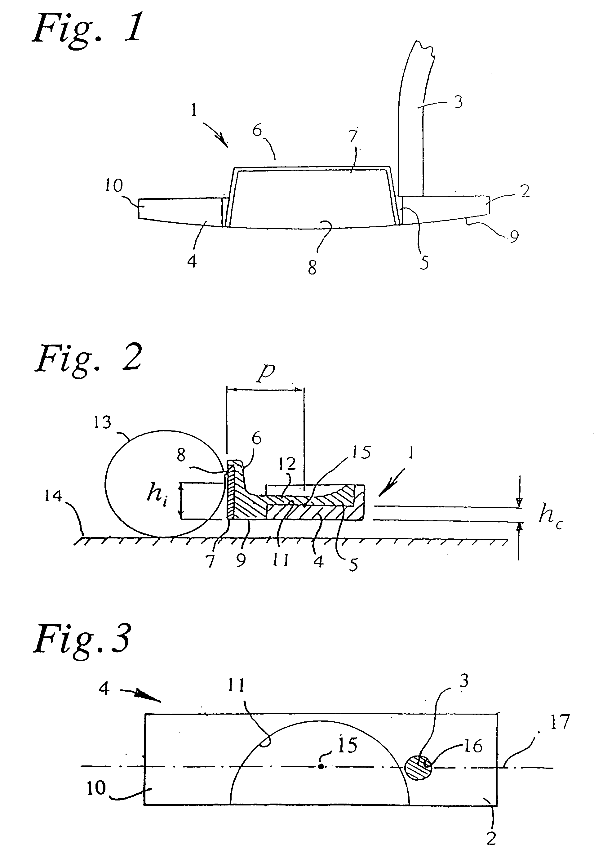
[0021] Referring to FIGS. 1 and 2, the putter-head 1, which is attached near its heel 2 to a putter-shaft 3, comprises a substantially flat-topped base 4, a bumper 5 bonded firmly to the base 4 and having an upstanding forward flange 6, and an element 7 that is inset in, and bonded to, the front of the flange 6 to provide the impact-face 8 of the head 1. The base 4 extends the length of the head 1 with a curved bottom or sole 9, to define the toe 10 of the head 1 as well as its heel 2.

[0022] In practice there may be departure from the somewhat strictly-rectangular configuration shown for the base 4, to incorporate stylistic features, angled surfaces and rounded edges. In order to conform to the Rules of Golf, the putter head of FIGS. 1 and 2 should have only one surface, namely impact-face 8, that can be used as an impact-face; the opposite, rear face and the toe and heel ends should thus contain features which prevent them from being usable in this regard.

[0023] As shown most cle...


PUM


Abstract

A putter-head (1) has its center of mass (15) spaced p mm behind its impact-face (8) at a height hc mm above the head-bottom (9), a loft angle α12 at height 12 mm above the head-bottom (9), a moment of inertia l kg-mm2 about the vertical axis through the center of mass (15), a mass M kg and a radius of gyration of K mm about the heel-toe axis (2-10) of the head through the center of mass (15), where p / l is not more than 0.18, hc is less than [12−p×sin(α12)]. The ratio d2 / K is less than 1.0, d2 mm being the vertical offset above the heel-toe axis (2-10) of the axis of attachment of the putter-shaft (3) to the putter-head (1); the attachment-axis of the shaft may be spaced by no more than the shaft-radius from the center of mass. The impact-face (36) may have an upper flat section (38) that merges smoothly into a cylindrical lower section (39), and the head (30) may be constructed with a high-density part (32;40) that extend lengthwise of the heel-toe axis and is either bonded to the underside of a lower-density part (31), or forms both an upstanding front flange (43) and a rear body-section (41) of larger mass than, and spaced from, the flange (43).

Description

[0001] This application is a continuation-in-part of U.S. patent application Ser. No. 10 / 488,152 filed with an effective filing date of Sep. 2, 2002 which is national stage completion of PCT / GB02 / 03995 filed Sep. 2, 2002 which claims priority from British Application Serial No. 0210581.5 filed May 9, 2002, British Application Serial No. 0209060.3 filed Apr. 20, 2002, British Application Serial No. 0205962.4 filed Mar. 14, 2002, British Application Serial No. 0130838.6 filed Dec. 22, 2001, and British Application Serial No. 0121261.2 filed Sep. 1, 2001.FIELD OF THE INVENTION [0002] This invention relates to putter-heads and is also concerned with putters including them. BACKGROUND OF THE INVENTION [0003] In putters, it is desirable to arrange that the putter-head behaves like a free body at impact and to control various parameters of the putter-head such as its principal moments of inertia, the position of its center of mass and the impact face shape in order to improve spin and velo...

Claims


Application Information

Patent Timeline
Patent Type & Authority Applications(United States)
IPC IPC(8): A63B53/02A63B53/04
CPCA63B53/02A63B53/0487A63B2053/0441A63B2053/0433A63B2053/0491A63B2053/0416A63B53/0441A63B53/0416A63B53/0433A63B60/00
Inventor LINDSAY, NORMAN MATHESON
Owner LINDSAY LTD
Why Eureka
Try Eureka