Auxiliary tool for handcrafting

a technology of auxiliary tools and handcrafts, applied in the field of handicrafts, can solve the problems of a large number of yo-yos and may be a burden, and achieve the effect of making quilt parts such as yo-yos easily and efficiently

Active Publication Date: 2011-12-13
CLOVER MFG CO LTD
View PDF17 Cites 7 Cited by
  • Summary
  • Abstract
  • Description
  • Claims
  • Application Information

AI Technical Summary

Benefits of technology

[0006]The present invention has been proposed under the above-described circumstances. It is, therefore, an object of the present invention to provide a handicraft assisting tool which makes it possible to make quilt parts such as yo-yos easily and efficiently.

Problems solved by technology

Yo-yo quilts require a large number of yo-yos depending on the design, and to make a large number of yo-yos may be a burden.

Method used


Image

  • Auxiliary tool for handcrafting
  • Auxiliary tool for handcrafting
  • Auxiliary tool for handcrafting

Examples


first embodiment

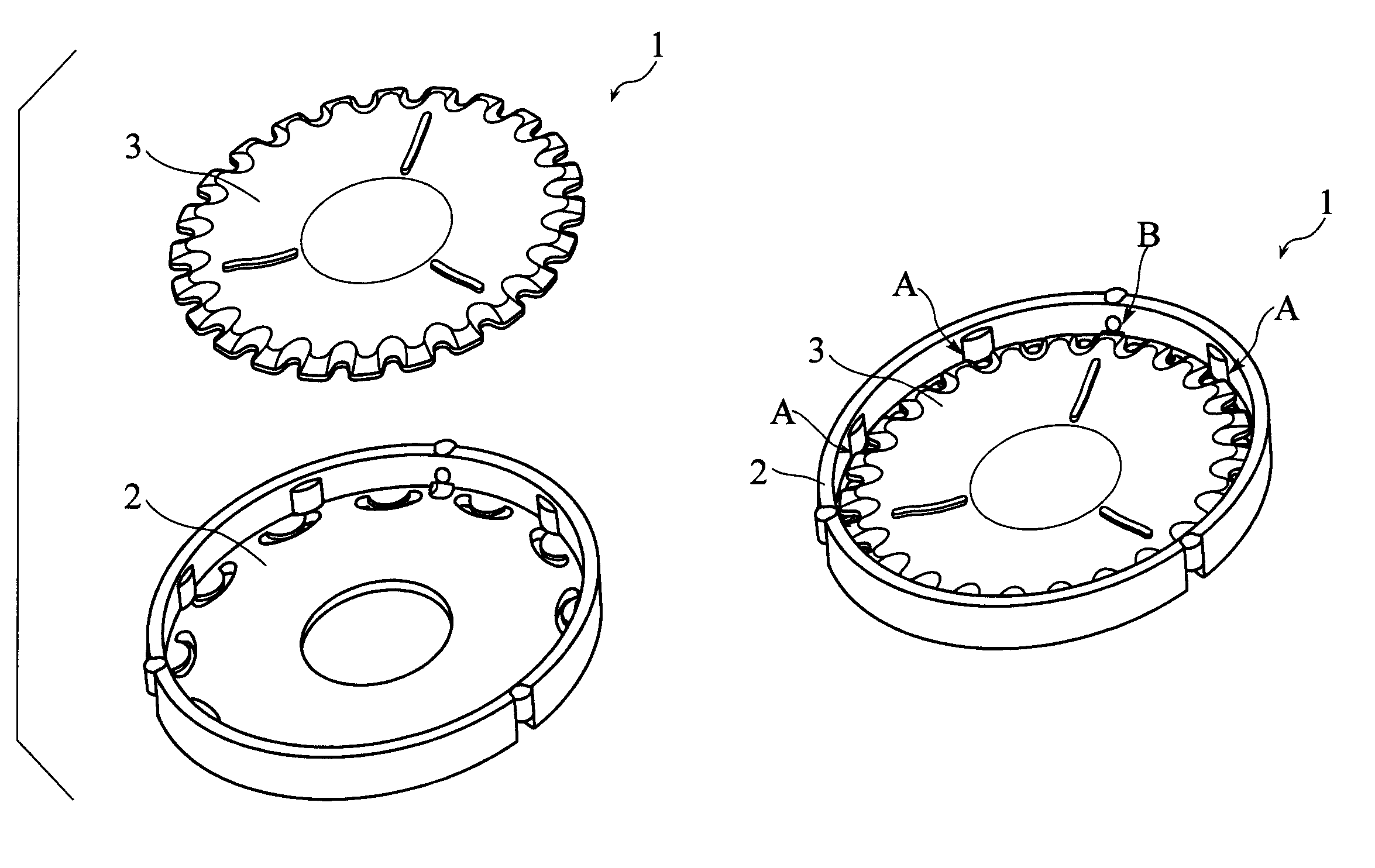
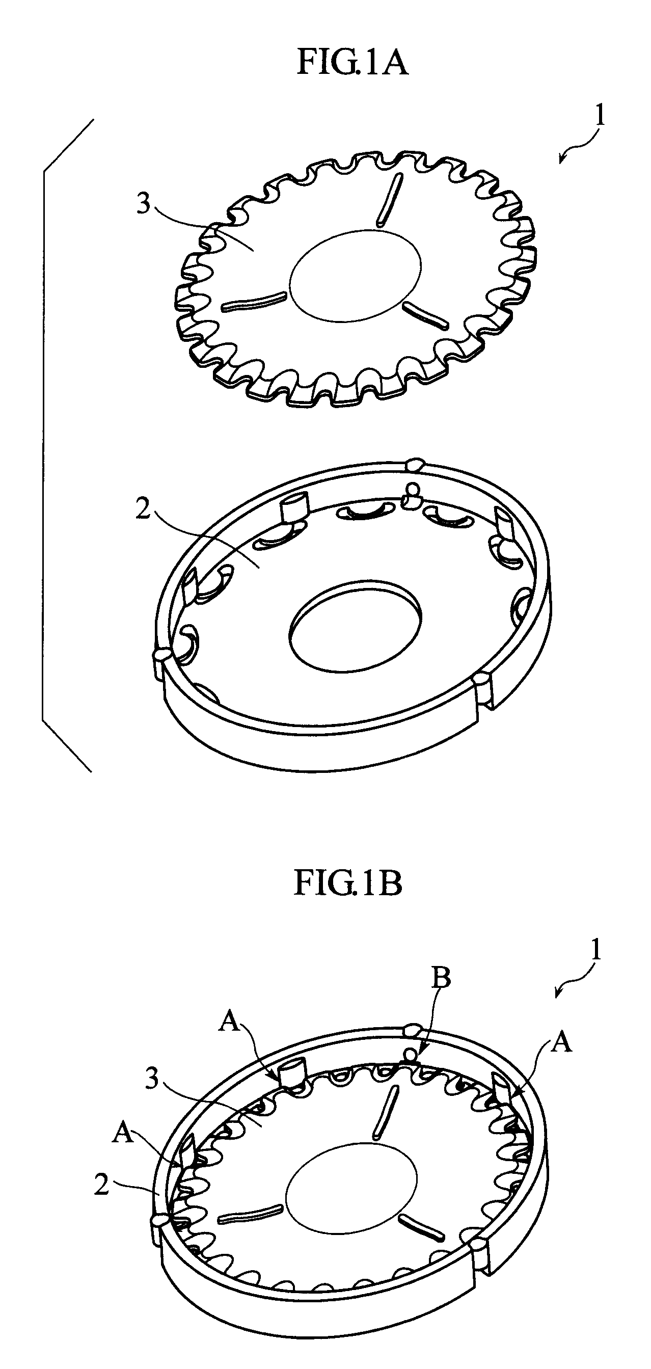
[0045]FIGS. 1A and 1B show a handicraft assisting tool according to the present invention. The handicraft assisting tool includes a supporting member 2 and a holding member 3. The handicraft assisting tool 1 further includes a rotation preventing mechanism A and a lock mechanism B, which will be described later. The handicraft assisting tool 1 is used for making a circular quilt part (yo-yo).

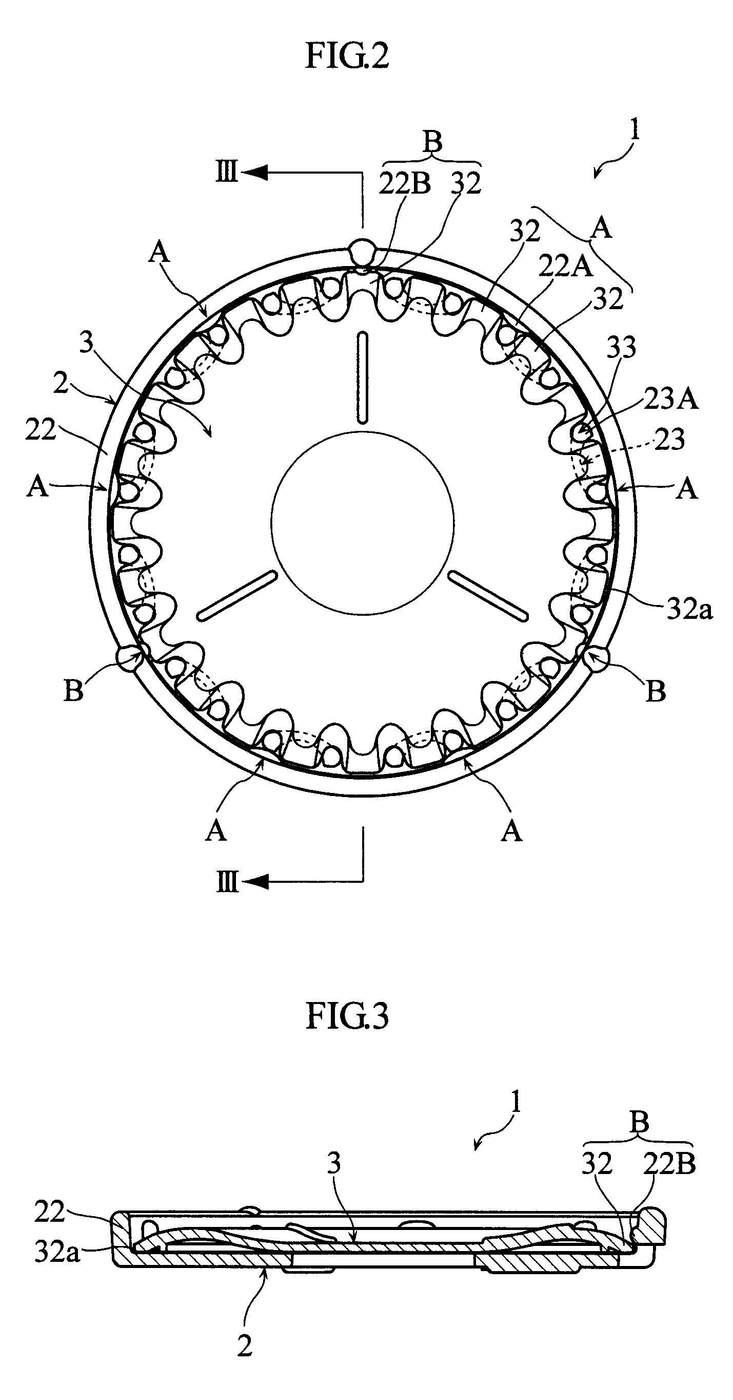
[0046]FIG. 1B shows the state in which the holding member 3 is properly placed on the supporting member 2. (Hereinafter, this state is referred to as “assembled state”.) In the actual use of the handicraft assisting tool 1 for making a yo-yo, material cloth is sandwiched between the supporting member 2 and the holding member 3 (see FIGS. 12 and 13). FIG. 2 is a plan view showing the assembled state. FIG. 3 is a sectional view taken along lines III-III in FIG. 2.

[0047]FIGS. 4-6 show the supporting member 2. As shown in the figures, the supporting member 2 includes a circular main plate 21 and a c...

third embodiment

[0079]As shown in FIG. 27, the holding member 3″ of the third embodiment is generally polygonal. The periphery of the holding member 3″ is formed with a plurality of projections 32″ and a plurality of recesses. The recesses include first recesses 33a″ which are relatively shallow and second recesses 33b″ which are relatively deep or large. The first recesses 33a″ communicate with the elongated holes 23α″ of the supporting member 2″, whereas the second recesses 33b″ communicate with the elongated holes 23β″. The holding member 3″ is further formed with a plurality of elongated holes 34″. The elongated holes 34″ are equally spaced from each other around the center O. Each of the elongated holes 34″ includes two generally arcuate ends having a dimension which allows smooth passing of a sewing needle and a middle portion connecting the two ends to each other. When the holding member 3″ is set to the supporting member 2″ (see FIG. 24), the two ends of each elongated hole 34″ communicate ...


PUM

PropertyMeasurementUnit
thicknessaaaaaaaaaa
diameteraaaaaaaaaa
diameteraaaaaaaaaa

Abstract

A handicraft assisting tool (1) includes a plate-like holding member (3) and a supporting member (2) on which the holding member is placed. The supporting member (2) includes a main plate having a shape corresponding to the holding member (3) and a side plate (22) standing from the periphery of the main plate in the thickness direction of the main plate. The main plate is formed with a plurality of elongated holes (23) arranged adjacent to the periphery of the main plate and spaced from each other along the periphery. The holding member (3) includes a periphery formed with a plurality of recesses (33). Each of the elongated holes (23) includes opposite ends configured to communicate with the recesses (33) when the holding member (3) is placed on the supporting member (2).

Description

TECHNICAL FIELD[0001]The present invention relates to an auxiliary assisting tool used in the field of handicraft such as patchworking.BACKGROUND ART[0002]Conventionally, in the field of handicraft such as patchworking, various tools for facilitating the making of handicraft have been proposed. For instance, Patent Document 1 given below discloses a pattern set for facilitating the work of cutting cloth in making a patchwork.[0003]Patent Document 1: JP-A-2004-169238[0004]A yo-yo quilt is known as one of patchwork quilts which has excellent decoration effect. A yo-yo quilt is made using e.g. a plurality of circular quilt parts (yo-yos). To make a yo-yo quilt, a plurality of yo-yos are first formed. A yo-yo is formed by folding back the edge of circular cloth, sewing the cloth along folded edge and then pulling and knotting the thread tightly. As shown in FIG. 19 of the present application, the yo-yo made in this way has a circular shape formed with gathers on the front side. By conne...

Claims


Application Information

Patent Timeline
Patent Type & Authority Patents(United States)
IPC IPC(8): D06C3/08G09B19/20A41H3/00
CPCD05B91/10D05C1/02
Inventor KUWABARA, JUNICHI
Owner CLOVER MFG CO LTD
Why Eureka
Try Eureka