
Sprinkler with variable arc and flow rate

a technology of variable arc and flow rate, which is applied in the direction of burners, lighting and heating apparatus, artistic surface treatment, etc., can solve the problems of inability to reduce the arc later, limited coverage of low angle, and inability to set the water distribution ar

Active Publication Date: 2011-12-13
RAIN BIRD CORP
View PDF222 Cites 59 Cited by
  • Summary
  • Abstract
  • Description
  • Claims
  • Application Information

AI Technical Summary

Problems solved by technology

Traditional variable arc sprinklers suffer from limitations with respect to setting the water distribution arc.
Others have used punch-outs to select a fixed water distribution arc, but once a distribution arc was set by removing some of the punch-outs, the arc could not later be reduced.
For rotating stream sprinklers, however, it is difficult to provide coverage for low angles, such as from about 0 degrees to about 90 degrees, because water flow may not be adequate at these low angles to impart sufficient force to the rotating deflector.
Because of the limited adjustability of the water distribution arc, use of such conventional sprinklers may result in overwatering or underwatering of surrounding terrain.
In such instances, given the limited flexibility in the types of water distribution arcs available, the use of multiple conventional sprinklers often results in an overlap in the water distribution arcs or in insufficient coverage.
Thus, certain portions of the terrain are overwatered, while other portions are not watered at all.
In this regard, in the absence of a flow rate adjustment device, the irrigation sprinkler will have limited variability in the throw radius of water distributed from the sprinkler, given relatively constant water pressure from a source.
The inability to adjust the throw radius results both in the wasteful watering of terrain that does not require irrigation or insufficient watering of terrain that does require irrigation.
Some designs provide only limited adjustability and, therefore, allow only a limited range over which water may be distributed by the sprinkler.
Conventional rotating stream sprinklers generally do not allow arc adjustment from the top of the sprinkler's cap.

Method used


Image

  • Sprinkler with variable arc and flow rate
  • Sprinkler with variable arc and flow rate
  • Sprinkler with variable arc and flow rate

Examples


first embodiment

[0085]First, as can be seen in FIG. 21, the cap 212 includes slots 208 in its top surface 256. The slots 208 allow access of the hand tool, preferably a screwdriver, into a chamber 210 beneath the cap 212 for engagement with a slotted top surface 214 of the arc adjustment member 234. A user may use the hand tool to rotate the arc adjustment member 234 to the desired arcuate span. The sprinkler 200 may include an additional seal about the top end of the arc adjustment member to limit the entry of grit and other debris past the top end. Rotation of the arc adjustment member 234 causes rotation of the valve sleeve 264 and controls the desired arcuate span in the same manner as described above for the An example of such a cap used in conjunction with a rotatable member having a slotted top surface is shown and described in U.S. Pat. No. 6,814,304. Other conventional methods may also be used to rotate the arc adjustment member 234.

[0086]Second, as can be seen in FIGS. 22 and 23, the spr...

third embodiment

[0091]In the third embodiment, as seen in FIGS. 24-26, the structures of the nozzle cover 362 and nozzle collar 328 have been modified. Each has an outer wall: the nozzle cover 362 has an upper outer wall 375 and the nozzle collar 328 has a lower outer wall 340. The lower outer wall 340 can be rotated by the user to effect rotation of the nozzle collar 328. The nozzle collar 328 therefore has its own full, circumferential outer wall 340 having a grip surface, and cut-out portions and access windows in the nozzle cover 362 are no longer necessary.

[0092]As shown in FIG. 26, the structure of the nozzle collar 328 is further modified so that it preferably includes two arcuate slots 329 and 331 in its top surface 333. The nozzle base 374 and nozzle cover 362 are held stationary with respect to one another by welding, screws, rivets, or other fastening methods through the two arcuate slots in the nozzle collar top surface 333. As can be seen from FIG. 26, the nozzle cover 362 is in rigid ...

sixth embodiment

[0126]As with the other preferred embodiments, the variable arc capability of sprinkler 700 results from the interaction of the nozzle cover 762 and valve sleeve 764. With respect to sprinkler 700, as discussed further below, the valve sleeve 764 preferably includes a flexible overmolded portion that is the helical engagement surface of the valve sleeve 764. The nozzle cover 762 is preferably the same as the nozzle cover 662 described and shown for the The nozzle cover 762 has a helical engagement surface 794 for engaging the overmolded portion 701 of the valve sleeve 764 for rotatably adjusting the angle of the arcuate slot 720. As with previous embodiments, the nozzle cover 762 and valve sleeve 764 also each preferably have fins to define edges of the water stream passing through the slot 720.

[0127]As shown in FIGS. 37-40, the valve sleeve 764 has a generally cylindrical shape, but it has a modified structure relative to the other preferred embodiments. The valve sleeve 764 prefe...


PUM


Abstract

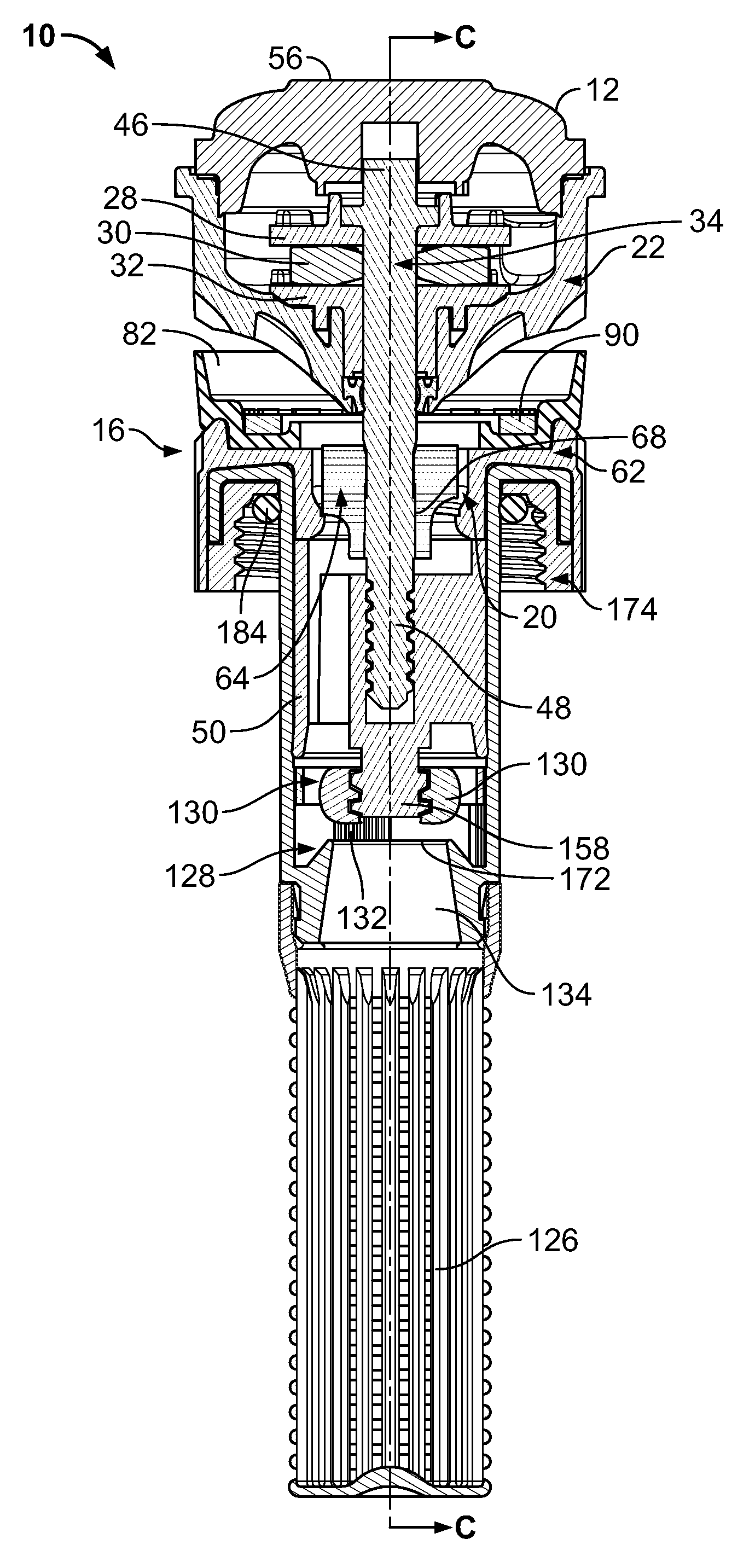
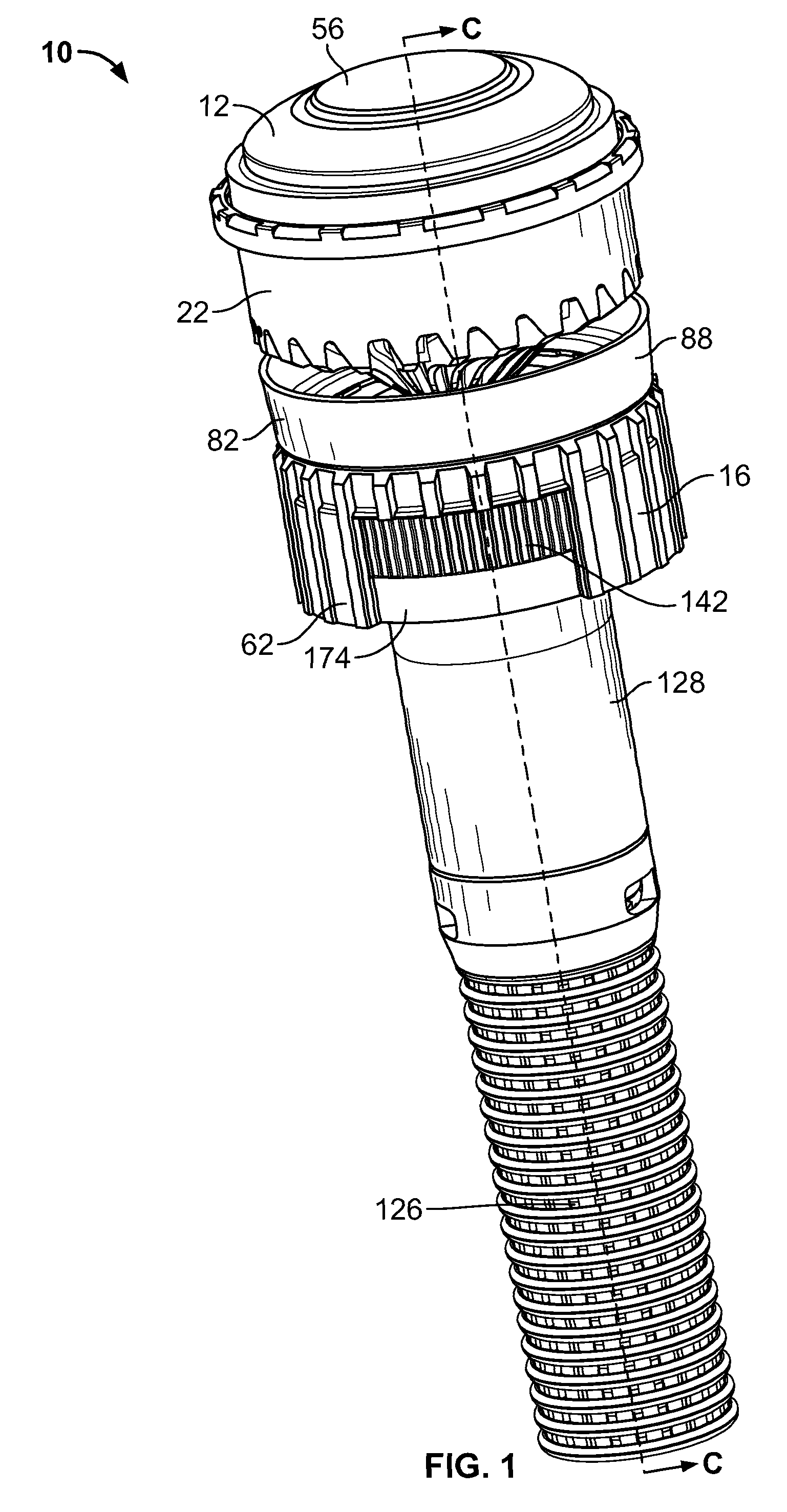
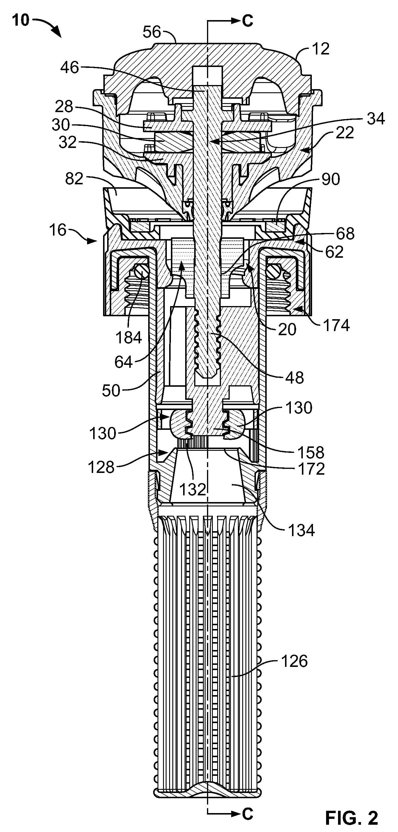
A variable arc sprinkler may be set to numerous positions along a continuum to adjust the arcuate span of the sprinkler. The sprinkler includes a nozzle body and a valve sleeve that helically engage each other to define an arcuate slot that may be adjusted at the top of the sprinkler to a desired arcuate span. The sprinkler may include a flow rate adjustment device that may be adjusted by actuation or rotation of an outer wall portion of the sprinkler. Rotation of the outer wall portion may cause a throttle control member to move axially to or away from an inlet, or may cause one or more restrictor elements to open or close, to control the flow rate of the sprinkler.

Description

FIELD OF THE INVENTION[0001]This invention relates to irrigation sprinklers and, more particularly, to an irrigation sprinkler for distribution of water through an adjustable arc and with an adjustable flow rate.BACKGROUND OF THE INVENTION[0002]The use of sprinklers is a common method of irrigating landscape and vegetation areas. In a typical irrigation system, various types of sprinklers are used to distribute water over a desired area, including rotating stream type and fixed spray pattern type sprinklers. One type of irrigation sprinkler is the rotating deflector or so-called micro-stream type having a rotatable vaned deflector for producing a plurality of relatively small water streams swept over a surrounding terrain area to irrigate adjacent vegetation.[0003]Rotating stream sprinklers of the type having a rotatable vaned deflector for producing a plurality of relatively small outwardly projected water streams are known in the art. In such sprinklers, one or more jets of water ...

Claims


Application Information

Patent Timeline
Patent Type & Authority Patents(United States)
IPC IPC(8): B05B3/04
CPCB05B3/003B05B1/304B05B3/0486B05B3/021
Inventor HUNNICUTT, STEVEN BRIANWALKER, SAMUEL C.JAHAN, ROWSHAN
Owner RAIN BIRD CORP
Learn More