
Appliance for controlling transparent or reflective elements

a technology of transparent or reflective elements and control devices, applied in the direction of optics, instruments, material analysis, etc., can solve the problems of limited existing measurement devices, hardly suitable for objects with variable surface characteristics, and difficult to switch from one model of objects to another, and achieve the effect of high degree of adaptability

Active Publication Date: 2011-12-20
AUTOMATION & ROBOTICS SA
View PDF18 Cites 17 Cited by
  • Summary
  • Abstract
  • Description
  • Claims
  • Application Information

AI Technical Summary

Benefits of technology

"The present invention provides a device that can detect and measure optical defects with high precision and adaptability. The device uses programmable optoelectronic means to produce a luminous background with a high spatial frequency, which is then collected by an artificial vision system. The device can inspect optical parts, read marks, observe discontinuities, and measure optical power or curvature. The device is flexible and can adapt to different methods, such as bright field or knife-edge methods."

Problems solved by technology

Moreover, and particularly for “large-size” objects, the various points of the object are not illuminated in the same way with this kind of device.
Thus, with the above-described device, a tangential scratch may very well be detected whereas an identical radial scratch may possibly not be observed.
It is known that deflecting defects and defects diffusing light at a low angle or in a narrow cone are advantageously detected with great sensitivity by “Schlieren techniques” which are, however, hardly suitable for objects with variable surface characteristics or for switching from one model of object to another.
Therefore, the problem that arises both for detecting defects in optical parts and for determining the optical properties of components, is that the existing measurement devices are limited, as a result of their relatively rigid configuration, to a restricted range of applications.

Method used


Image

  • Appliance for controlling transparent or reflective elements
  • Appliance for controlling transparent or reflective elements
  • Appliance for controlling transparent or reflective elements

Examples


Embodiment Construction

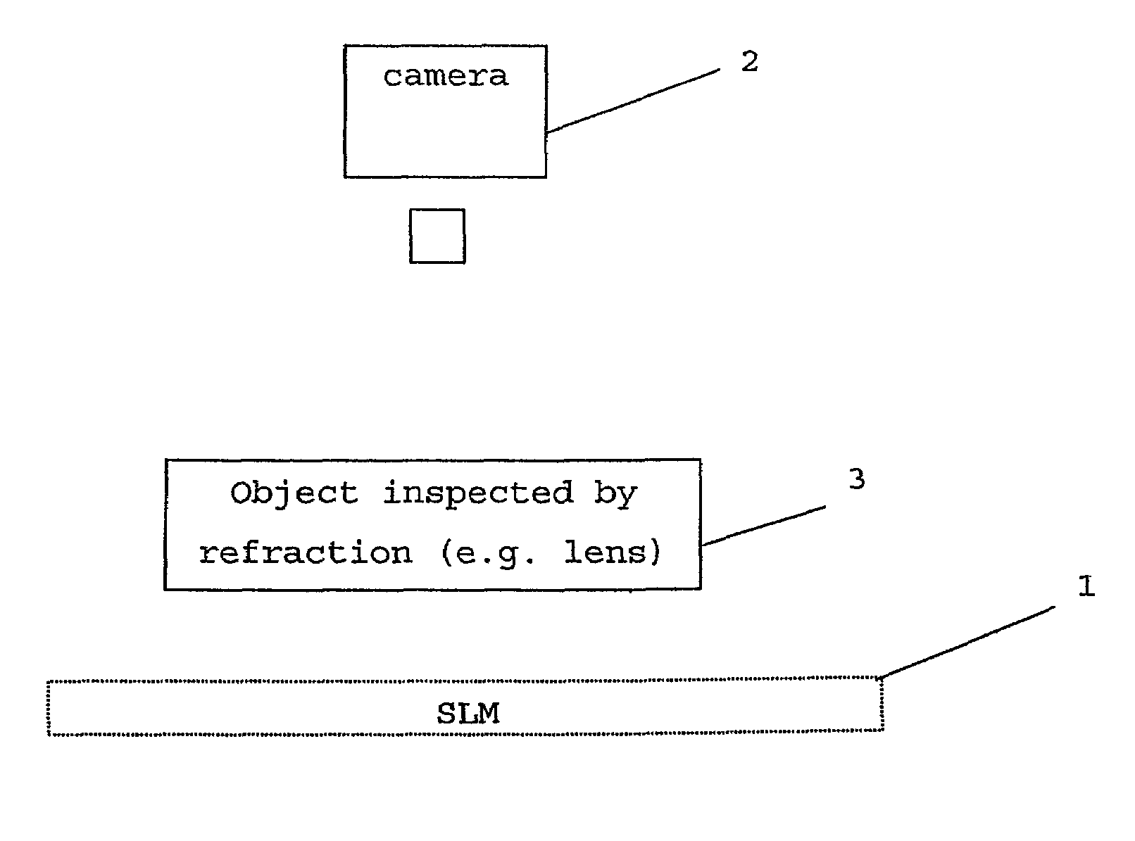
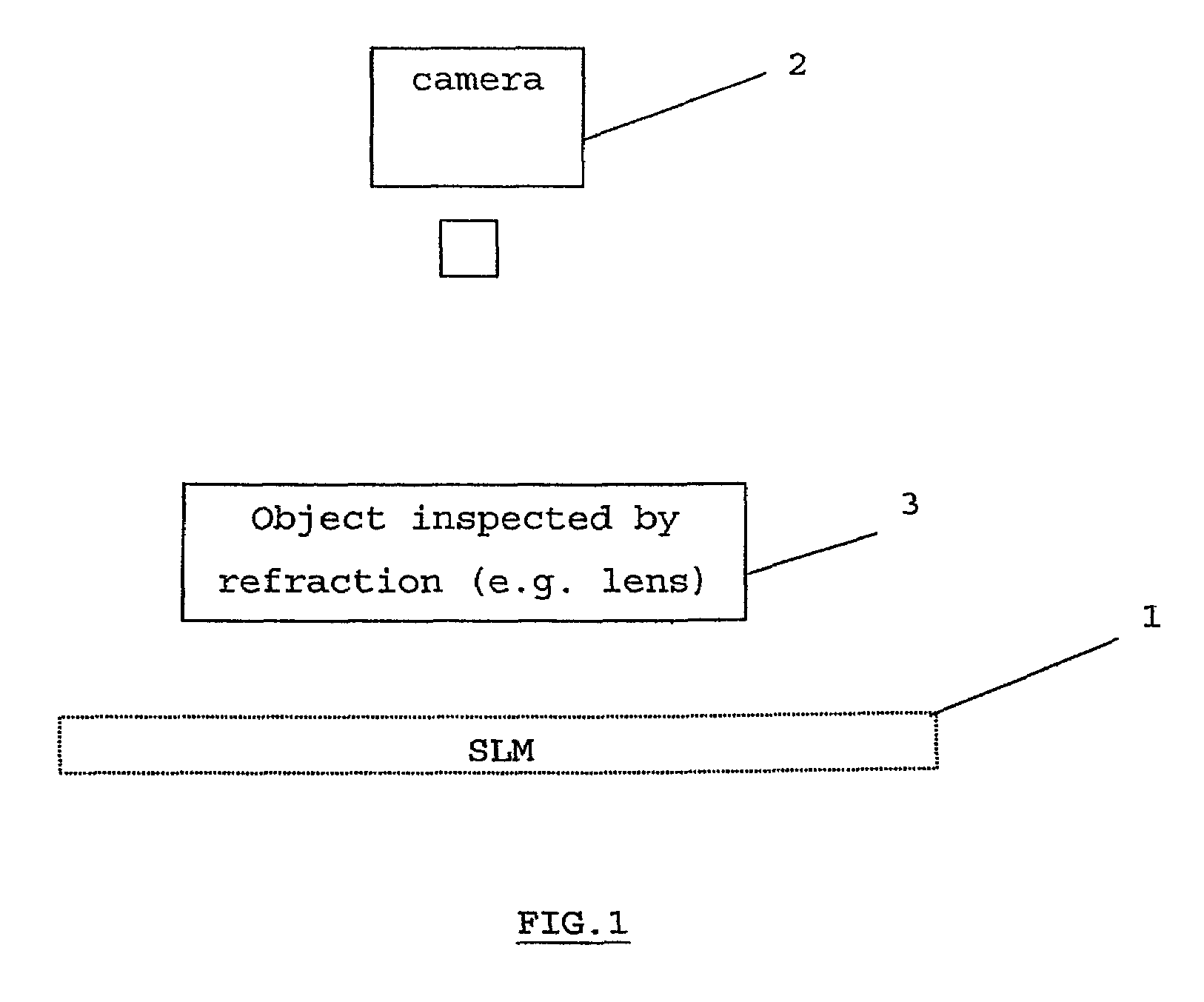
[0035]As very schematically shown in FIG. 1, the present invention relates to the use of a spatial light modulator or SLM 1, for example a liquid crystal display (LCD) screen providing in a flexible, variable and precise way a lighting device associated with a camera 2, for example a CCD or CMOS camera, with or without an object lens, in order to inspect an optical object 3, in particular, for example, for detecting defects, reading marks (moulded or engraved), observing discontinuities (edge of the lens) or tracing the outline of a segment of a multifocal lens, measuring optical properties, and to do this by generating suitable definition charts or dots of a suitable size at positions selected ad hoc.

[0036]In the broadest sense, an SLM is a lighting device that allows the digital or analogue control of the light intensity and of the local colour that it produces, transmits or reflects at any point, possibly in a determined direction.

[0037]An SLM is usually an electro-optical device...


PUM

PropertyMeasurementUnit
angleaaaaaaaaaa
angleaaaaaaaaaa
sizesaaaaaaaaaa

Abstract

The invention relates to an appliance for measuring or controlling an optical element (3) comprising illumination means (1) and an associated artificial vision system (2), in which the optical element (3) can be inserted between the illumination means (1) and the artificial vision system (2), said illumination means (1) comprising programmable optoelectronic means for producing a luminous background with spatially and temporally variable brightness. The inventive appliance is characterised in that the programmable optoelectronic means are embodied in such a way as to consecutively generate a plurality of mires, each comprising a pattern which is repeated in a contrasted manner on a uniform background with a high spatial frequency of between 0.01 and 100 patterns / mm, or such that two adjacent patterns are separated by an angle between 0.1 and 30 degrees, said angle being measured from the point of the object on which the pattern is observed. Said generated mires are consecutively spatially staggered in such a way that a plurality of images corresponding to the mires is captured by the artificial vision system after reflection or transmission by the optical element (3), and recombined in the form of a single composed image.

Description

CROSS-REFERENCE TO RELATED PATENT APPLICATIONS[0001]This patent application is the National Stage of International Application No. PCT / BE2005 / 000094 filed Jun. 8, 2005, that claims the benefit of European Application No. 04447138.1 filed Jun. 9, 2004.FIELD OF THE INVENTION[0002]The present invention relates to a device for:[0003]detecting defects or locating semi-visible marks present in transparent or reflective optical parts, for example detecting deformations and appearance defects (“cosmetic control”);[0004]measuring the optical properties of such optical parts (for example characteristics of divergence, refraction, transmission factor, power or vergence, curvature, diffusivity, etc.).[0005]One example application area of the invention is the control of optical lenses and of all transparent and / or reflective products in the ophthalmic industry.[0006]A reflective product is defined a priori as being a product with a surface that reacts to incident light according to the law of sp...

Claims


Application Information

Patent Timeline
Patent Type & Authority Patents(United States)
IPC IPC(8): G06K9/00G01N21/00G02F1/03G01M11/02
CPCG01M11/02
Inventor LAURENT, CHRISTIAN
Owner AUTOMATION & ROBOTICS SA
Learn More