Toilet and toilet seat mounting system

a toilet seat and mounting system technology, applied in the field of toilet seat mounting system, can solve the problems of difficult access to the area around the interconnection, difficult cleaning and sanitizing, and disaffection of maintenance in the area, so as to facilitate cleaning of the toilet seat and cover, the seat mounting system and the surrounding environment, and maximize the exposure of the seat, the cover and the bowl for maintenance.

Active Publication Date: 2011-12-27
LEIBFRIED MICHAEL R
View PDF50 Cites 9 Cited by
  • Summary
  • Abstract
  • Description
  • Claims
  • Application Information

AI Technical Summary

Benefits of technology

[0005]This invention relates to toilets and toilet seats and more particularly to a toilet seat mounting system that overcomes the shortcomings in the prior art as discussed above. The invention is advantageous both in systems employing only a seat, generally termed “commercial style” and systems utilizing both a seat and seat cover, generally termed “residential style.” In accordance with this invention a mounting system is provided that maintains a toilet seat, or seat and cover, in three distinct positions. The system includes apparatus that maintains the seat or the seat and cover in the conventional use position or down position, aligned with and supported on the bowl flange. The apparatus also permits rotation of the cover, or the seat and cover, to a conventional over center storage position. In addition to the conventional use position and the conventional over center storage position, the apparatus of the invention is unique in that it permits controlled upward movement of the seat or the seat and cover to an unconventional elevated over center maintenance position substantially above the bowl flange. This unique position maximizes exposure of the seat, the cover and the bowl for maintenance. This facilitates cleaning the toilet bowl and bowl flange, the toilet seat and cover, the seat mounting system and the surrounding environment, without the need to detach the seat, or the seat and cover, from the toilet bowl fixture.
[0006]This invention provides increased stability and rigidity of the seat, or seat and cover, when resting on the bowl flange in both the conventional use position and in the over-center storage position. Moreover, this invention provides positive support of the seat, or seat and cover, in the maintenance position above the bowl flange providing enhanced clearance and access, to better facilitate cleaning and maintenance. This ease of access is accomplished with a system comprising two elongate posts each extending downwardly from an over-molded post holder that rests on the bowl flange. Each post extends downwardly from the mounting apparatus and each is slidably mounted in a respective post receptacle which passes through and is positively secured within a toilet bowl flange aperture. Two vertical posts may be integrated into a single elongate double post holder extending between the bowl apertures. The double post holder may interface with a seat and cover in the conventional way using one or two hinge pins to allow the seat and the cover to rotate independently. Alternatively, the double post holder may be integrally molded with the seat and cover mounting apparatus in a more unconventional method such as a flexible hinge or “live hinge” without hinge pins connecting the double post holder, seat and cover to facilitate independent rotation of the seat and cover to their respective positions.
[0007]Each post receptacle is rigidly secured in the bowl flange aperture with a bushing to insure a positive rigid location of the receptacle. Each receptacle is secured and fastened in the respective bowl flange aperture by a cylindrical receptacle retainer. The post receptacles and receptacle retainers provide adequate fastening and support for the entire assembly and close the bowl flange apertures against contamination. The post receptacles are internally configured to insure a sliding fit with the posts. Each post has distal interference means which releasably engages the receptacle to, in turn, releasably support the post in the elevated maintenance position. The seat, or seat and cover, are easily raised to the elevated cleaning and maintenance position and lowered to rest on the bowl flange when and as desired.

Problems solved by technology

It has been found that cleaning and sanitizing is complicated by the intricacies of hinge-like interconnections between the pivoted seat ring and the bowl flange of a toilet bowl and by the inconvenient location and the often unsavory condition thereof.
In many installations the problems are aggravated by the hinge-like interconnection of a separate seat cover mounted above the seat.
Access to the area around those interconnections is difficult and inconvenient and maintenance in that area is often distasteful.
This approach presents additional problems for maintenance personnel.
This results in excessive handling and touching of contaminated toilet seats, and subjects additional surface areas to contamination.
The open apertures in the bowl flange bushing will collect debris and cleaning materials that are difficult to remove.
Moreover, a configuration relying on total separation of the seat assembly from the toilet bowl will be more subject to vandalism and theft, especially in commercial applications.
Such arrangements also present the problems of excessive handling and touching of the unsanitary detached seat, or seat and cover assembly, and a tendency to place it on remote surfaces for cleaning and sanitizing.
Such an approach using releasable fasteners creates additional new problems.
The protruding bowl flange ball creates new problems in bowl flange maintenance and the complex exposed fastener with a tab and socket present additional difficulties in removing and remotely resting the seat for maintenance.

Method used


Image

  • Toilet and toilet seat mounting system
  • Toilet and toilet seat mounting system
  • Toilet and toilet seat mounting system

Examples


Embodiment Construction

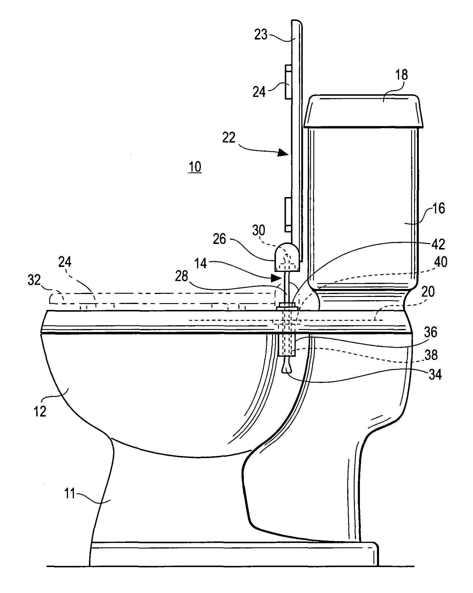
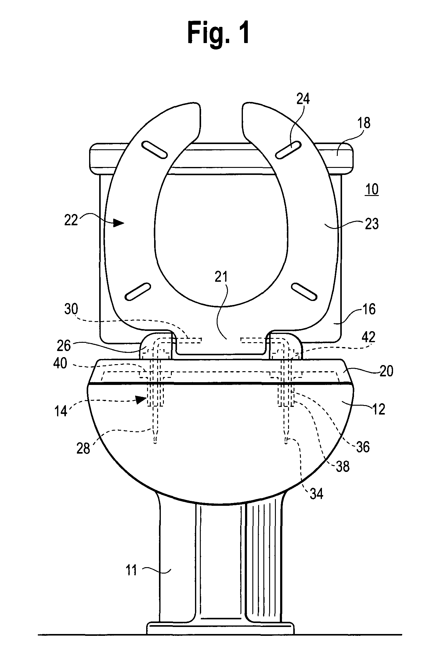
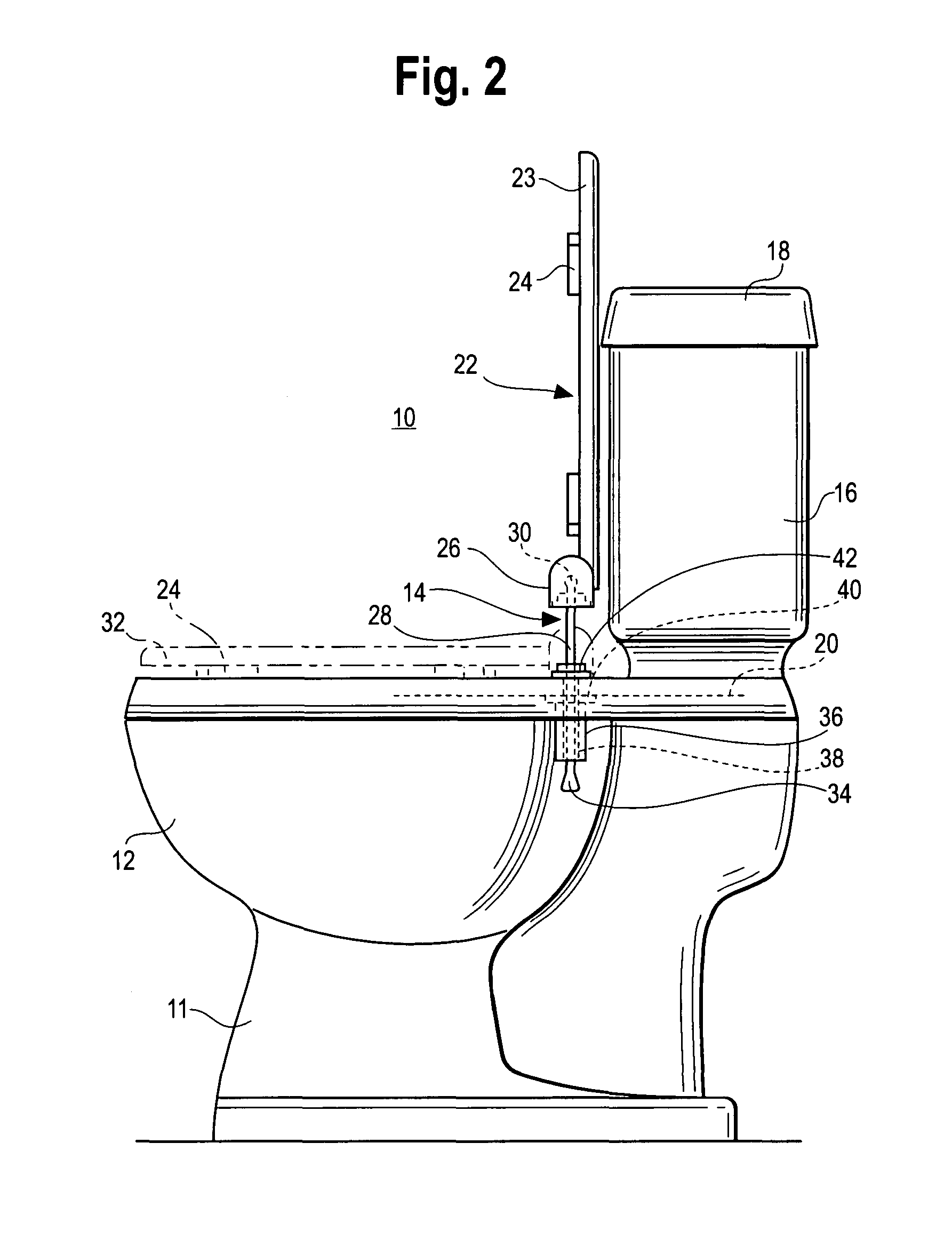
[0027]The invention disclosed herein is set forth in the following description, is illustrated in the attached drawings and is the subject of the attached claims. The embodiments of the invention shown and described hereinafter are examples that further illustrate the invention but should not be construed as in any way limiting the scope of the claims. For example, specific configurations are illustrated in the drawings for mounting the seat ring but the mounting means can vary widely within the scope of this invention.

[0028]Referring to the drawings and particularly to FIGS. 1 and 2, a typical commercial toilet 10 is shown having a toilet bowl 12 on a base 11 with a water tank 16 and a tank cover 18. A seat 22 can assume three distinct positions relative to the bowl. The bowl 12 has a bowl flange 20 with apertures 40 and a mounting system secured in the apertures 40 which supports the seat 22. The seat 22 is shown: in the over center storage position on the bowl flange 20 (solid li...


PUM


Abstract

A toilet including a toilet bowl having a bowl flange with apertures, a toilet seat, a toilet seat cover and mounting apparatus. The seat comprises a seat ring configured to rest on the bowl flange and seat mounting means and the seat cover comprises a cover and cover mounting means. The mounting apparatus includes the seat mounting means, the cover mounting means, post holders which overlie the bowl flange apertures, and connecting means joining said seat and cover mounting means and the post holders to permit rotation of the seat ring and cover between a generally horizontal use position and an over center storage position. An elongate post is secured to and extends downwardly from each of the post holders. A post receptacle is positively secured in each of the bowl flange apertures and extends there beyond. A cylindrical receptacle retainer surrounds and engages each receptacle over most of its length and engages the underside of the bowl to positively secure the receptacle in the bowl flange aperture. The elongate posts extend downwardly from each of the post holders and pass through and beyond the aligned receptacles. The posts have sufficient length to permit the seat to be elevated above the bowl flange to the over center maintenance position to provide adequate space for easy maintenance. Each post has distal means configured to engage the respective receptacle and to releasably support the post in the maintenance position for cleaning and maintenance.

Description

CROSS-REFERENCE TO RELATED APPLICATIONS[0001]This patent application is a continuation in part of Utility patent application Ser. No. 11 / 581,900 filed Oct. 17, 2006 which claims the benefit of U.S. Provisional Patent Application No. 60 / 729,084, filed Oct. 21, 2005.BACKGROUND OF THE INVENTION[0002]Improving the maintenance, the cleanliness and the sanitation features of conventional toilets and toilet seats has been the subject of many efforts to provide improved toilet seats, toilet bowls and means for connecting them. It has been found that cleaning and sanitizing is complicated by the intricacies of hinge-like interconnections between the pivoted seat ring and the bowl flange of a toilet bowl and by the inconvenient location and the often unsavory condition thereof. In many installations the problems are aggravated by the hinge-like interconnection of a separate seat cover mounted above the seat. Access to the area around those interconnections is difficult and inconvenient and ma...

Claims


Application Information

Patent Timeline
Patent Type & Authority Patents(United States)
IPC IPC(8): A47K13/00
CPCA47K13/26
Inventor LEIBFRIED, MICHAEL R.
Owner LEIBFRIED MICHAEL R
Why Eureka
Try Eureka