Ventilated deck drainage systems

a drainage system and ventilation technology, applied in the field of deck drainage system, can solve the problems of rotting of the deck structure, inability to allow air and gas to circulate between the cavities,

Inactive Publication Date: 2011-12-27
BUTLER DAVID LEE +1
View PDF41 Cites 14 Cited by
  • Summary
  • Abstract
  • Description
  • Claims
  • Application Information

AI Technical Summary

Problems solved by technology

All of these systems, however, do not allow air and gases to circulate between a cavity formed by the deck and the deck drainage systems.
By not allowing gases to circulate, moisture collects within the cavity and enables mold, fungus, and bacteria to grow, as well as potentially leading to rotting of the deck structure.

Method used


Image

  • Ventilated deck drainage systems
  • Ventilated deck drainage systems
  • Ventilated deck drainage systems

Examples


Embodiment Construction

[0012]Various embodiments are described more fully below with reference to the accompanying drawings, which form a part hereof, and which show specific embodiments for practicing the invention. However, embodiments may be implemented in many different forms and should not be construed as limited to the embodiments set forth herein; rather, these embodiments are provided so that this disclosure will be thorough and complete, and will fully convey the scope of the invention to those skilled in the art. Embodiments may be practiced as methods, systems or devices. Accordingly, the following detailed description is, therefore, not to be taken in a limiting sense.

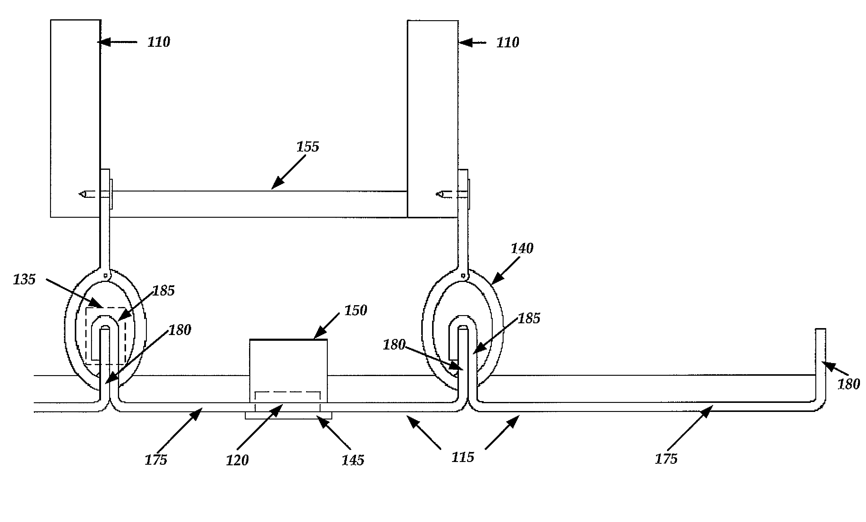
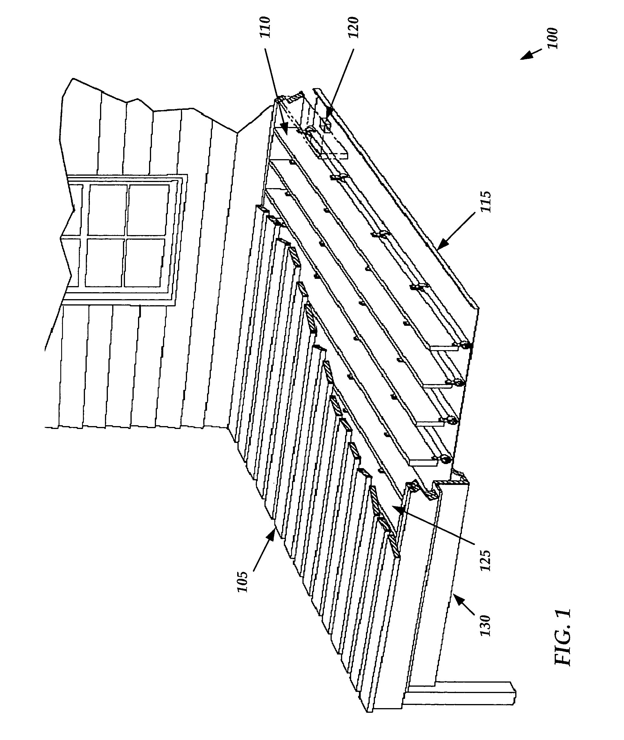
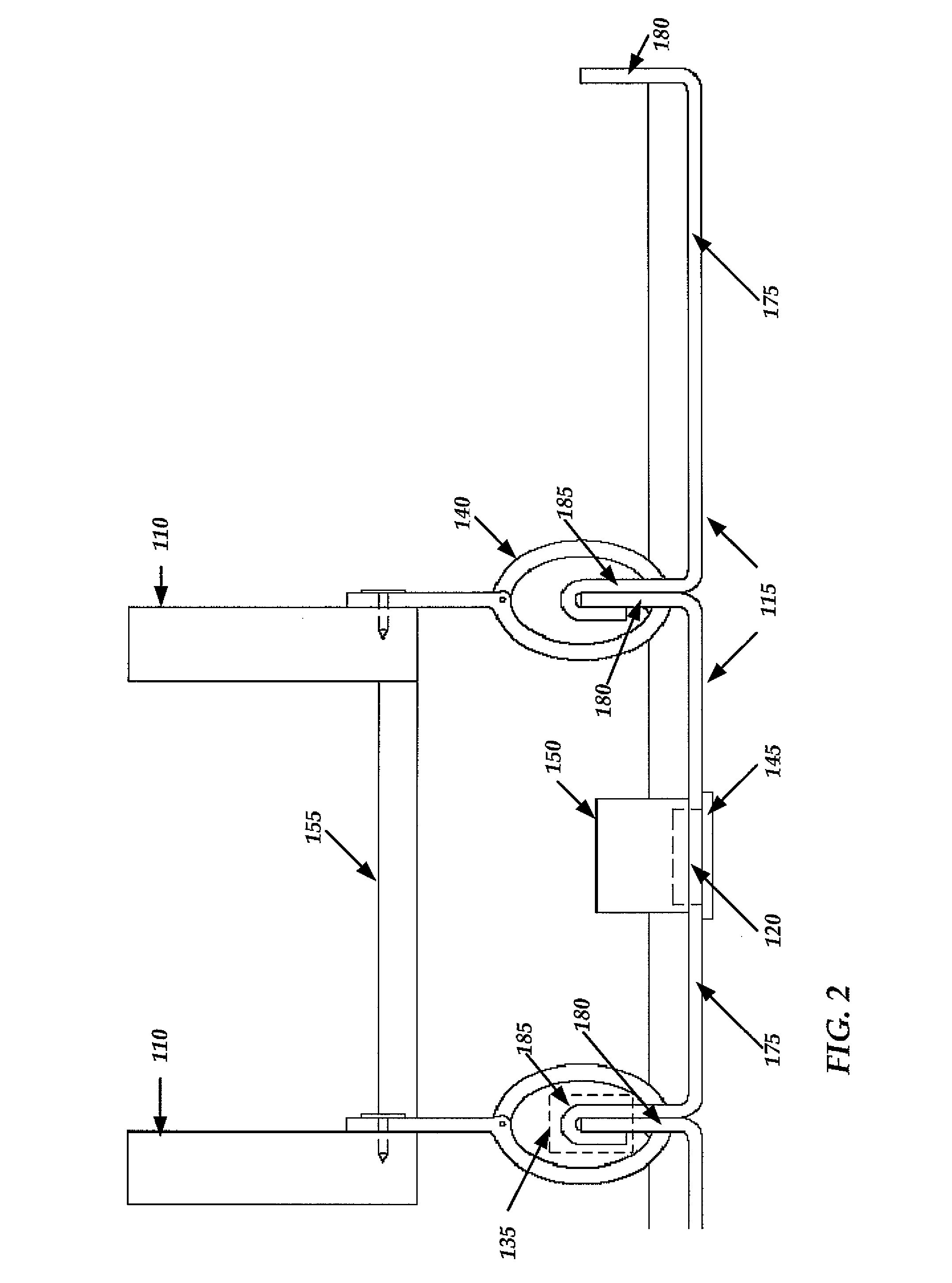
[0013]Referring more particularly to the drawings, FIG. 1 depicts a deck drain vent system 100 consistent with embodiments of the present invention. The deck drain vent system 100 includes a deck 105 including a joist 110 and at least one panel 115 located beneath the deck 105. The panel 115 of the deck drain vent system 100 incl...


PUM


Abstract

A system and method for providing a deck drain vent system is disclosed. The deck drain vent system includes at least one panel disposed below a lower surface of a deck. The panel is substantially planar and has a bottom side and a top side facing and spaced apart from the lower surface. At least one vent penetrates the panel to allow fluid communication between the cavity and the bottom side. The deck drain vent system further includes a shaft lock secured to the vent. The shaft lock hinders liquids and debris from entering the vent, yet allows air to freely circulate between the cavity and a surrounding atmosphere.

Description

CROSS-REFERENCE TO RELATED APPLICATIONS[0001]This application is related to U.S. Provisional Application having Ser. No. 60 / 749,653 filed on Dec. 12, 2005, which is incorporated herein by reference in its entirety. This application is further related to U.S. Provisional Application having Ser. No. 60 / 751,488 filed on Dec. 19, 2005, which is incorporated herein by reference in its entirety.FIELD OF INVENTION[0002]The present invention generally relates to deck drainage systems. More particularly, the present invention relates to a deck drainage system that includes a ventilation system for allowing gas to circulate between a cavity formed by the deck drainage system and the adjacent deck such that water vapor may escape and not collect within the cavity.BACKGROUND OF THE INVENTION[0003]There are a multitude of deck drainage systems designed to catch liquids and solids which pass through spacing of deck boards. All of these systems, however, do not allow air and gases to circulate bet...

Claims


Application Information

Patent Timeline
Patent Type & Authority Patents(United States)
IPC IPC(8): E04B1/70E04B1/66E04B7/00E04F17/00E04D13/00F24F13/20
CPCE04B1/003E04F15/02183E04F17/00E04F2015/02055
Inventor BUTLER, DAVID LEESCLAFANI, ANTHONY JAMES
Owner BUTLER DAVID LEE
Why Eureka
Try Eureka