
Perimeter

a technology of perimeter and ophthalmology, applied in the field of perimeter, can solve the problems of high possibility of subject's erroneous responses, high discrepancy between the chart and the subject, and failure to detect early visual defects

Active Publication Date: 2011-12-27
TOMOHIRO TSUTA MASTERS DEGREE OF ECONOMICS OF THE UNIV OF TOKYO
View PDF15 Cites 0 Cited by
  • Summary
  • Abstract
  • Description
  • Claims
  • Application Information

AI Technical Summary

Benefits of technology

The system provides detailed visual field mapping images that accurately represent scotoma, blind spots, and declining visual function regions, reducing monotony and improving early detection of visual defects.

Problems solved by technology

There exists a considerable discrepancy between the chart resulted from a previous visual field examination and the shape of scotoma and blind spot true to the subject, since the shapes of scotoma and blind spot detected by previous perimeters are very rough.
It is because of relying on previous perimeters that the early detection of visual defects has been failing.
And there is the high possibility of erroneous responses made by the subject due to habituation, etc., because procedures of previous examinations are made up of very monotonous repetitions.

Method used


Image

  • Perimeter
  • Perimeter
  • Perimeter

Examples


Embodiment Construction

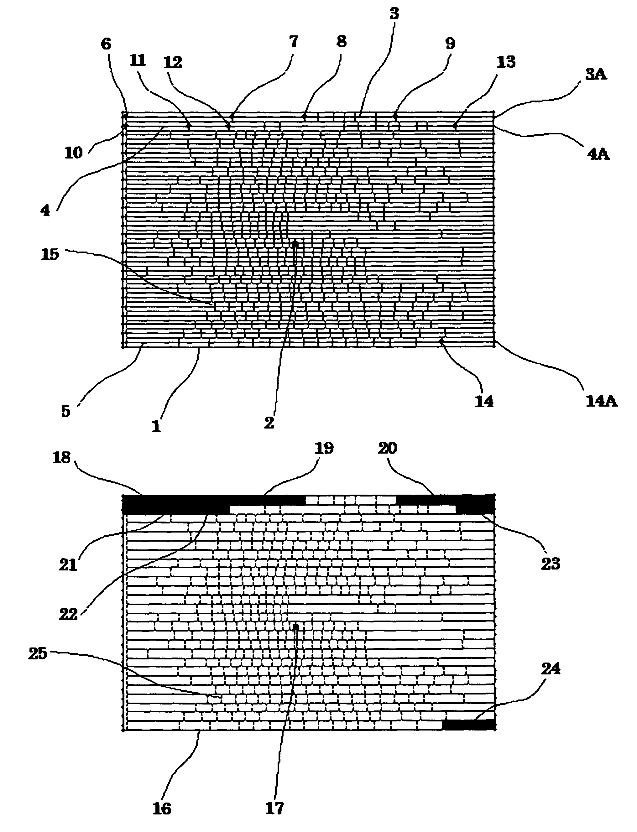
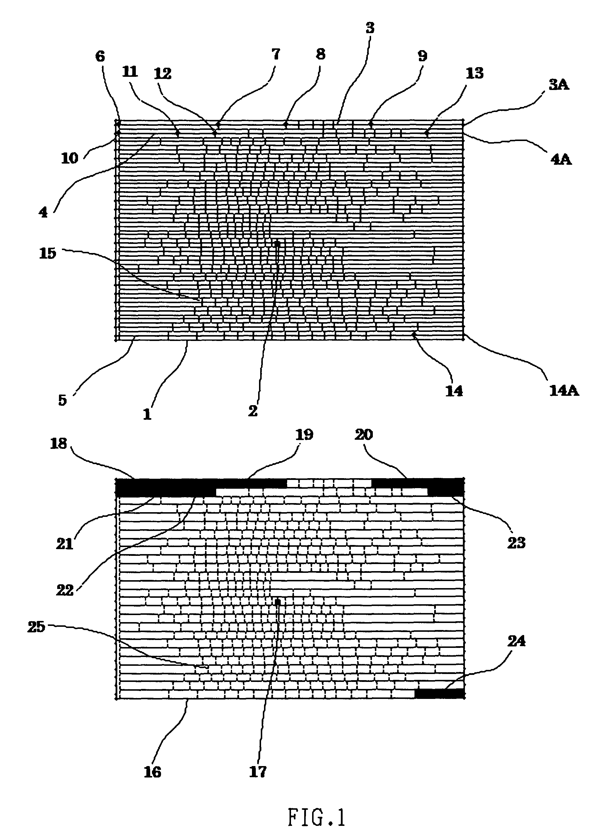
[0069]The detailed explanation of the present invention of a perimeter, an operational method of a perimeter, a program for realizing a perimeter, and a computer-readable recorded medium will be disclosed as below while referring to the drawings.

[0070]Firstly, a setup of the present invention of the perimeter is described referring to FIG. 3 and FIG. 6.

[0071]FIG. 3 shows an embodiment of the system of the present invention of the perimeter.

[0072]FIG. 6 shows an embodiment of the hardware configuration of the CPU 501 in the present invention of the perimeter.

[0073]FIG. 3 shows a computer system 301 diagrammatically.

[0074]The present invention of the perimeter is realized by the computer system 301 carrying out a program for realizing a perimeter.

[0075]As shown in FIG. 3, the computer system 301 realizing an embodiment of the present invention of the perimeter includes a main unit 302 that is equipped with a CPU (Central Processing Unit) 501, etc., which will be mentioned later, a key...


PUM


Abstract

A perimeter of the present invention including: visual field scanning screen generating means; fixation image displaying and controlling means; visual target scan line parallel setting means; statically displaying and controlling means; static display position storing means; static display and control stopping means; kinetic display and control starting means; detecting means; detection position storing means; distance storing means; kinetic scan stopping means; and scanning continuation means to the position of the visual target stored by the detection position storing means.

Description

BACKGROUND OF THE INVENTION[0001]The present invention relates to a perimeter, an operational method of a perimeter, a program for realizing a perimeter, and a computer-readable recorded medium.[0002]The following are known as previous perimeters: Goldmann perimeter of 510 model [1945], 940 model [1967]; Tubinger perimeter [1957]; Octopus perimeter [1976]. (see, for example, the nonpatent literature 1.)[0003]The explanation of previous perimeters: Goldmann perimeter is the first brightness perimeter, adopting manual method of simultaneous recording, with 4 to 60 degrees of brightness of the visual target and 6 types of visual angle of the visual target, capable of examining visual field of visual angle, and with adjustability of its background brightness. The shortcoming is that it fails to examine the central region within 5 degrees;[0004]Tubinger perimeter [1957] is the first practical, static perimeter, capable of examining the kinetic visual field and the visual field of color, ...

Claims


Application Information

Patent Timeline
Patent Type & Authority Patents(United States)
IPC IPC(8): A61B3/02A61B3/00
CPCA61B3/0091A61B3/024
Inventor TSUTA, TOMOHIRO
Owner TOMOHIRO TSUTA MASTERS DEGREE OF ECONOMICS OF THE UNIV OF TOKYO
Learn More