Plasma processing device and plasma generating method

一种等离子体、处理设备的技术,应用在离子体产生领域,能够解决变形、功率不会有效地提供等问题

Inactive Publication Date: 2008-12-03
TOKYO ELECTRON LTD +3
View PDF3 Cites 0 Cited by
  • Summary
  • Abstract
  • Description
  • Claims
  • Application Information

AI Technical Summary

Problems solved by technology

Therefore, since the cylindrical waveguide 512 is locally heated by the standing wave between the high frequency generator 511 and the load matching unit 514, it may be deformed
Also, power may not be efficiently delivered to the load side of the RLSA 515

Method used


Image

  • Plasma processing device and plasma generating method
  • Plasma processing device and plasma generating method
  • Plasma processing device and plasma generating method

Examples


no. 1 example

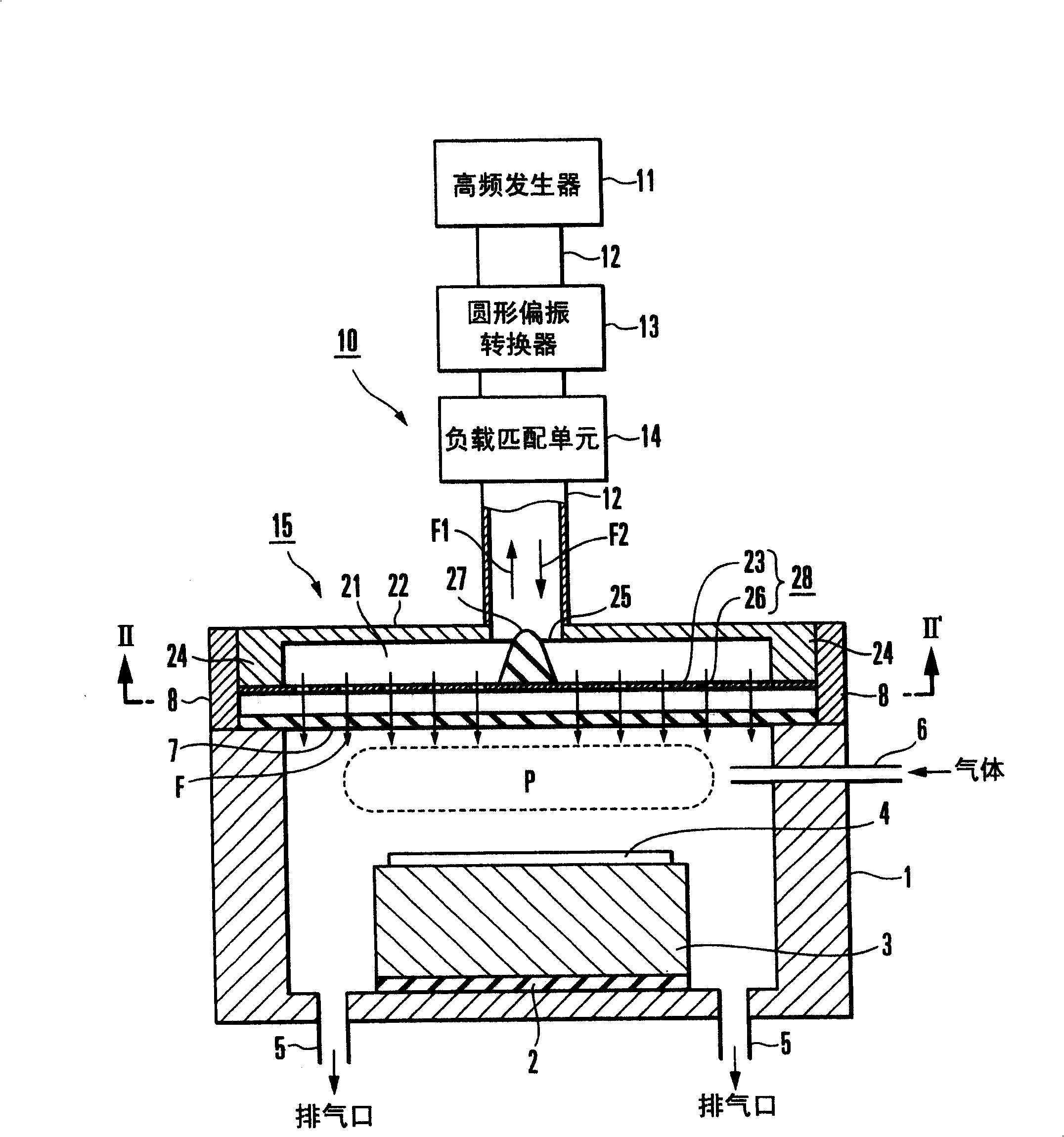
[0032] Attach the reference figure 1 to 4 describe the plasma processing apparatus according to the first embodiment of the present invention. figure 1 is a view showing the general arrangement of the first embodiment. This plasma processing apparatus has a processing container 1 which accommodates a substrate 4 such as a semiconductor or an LCD as a target object and processes the substrate 4 with plasma; and an electromagnetic field supply device 10 which supplies The high-frequency electromagnetic field F is such that plasma P is generated in the processing container 1 by the operation of the high-frequency electromagnetic field F.

[0033]The processing container 1 is a bottomed cylinder with an upper opening. A substrate table (table) 3 is fixed to the center portion of the bottom plane of the processing container 1 via an insulating plate 2 . A substrate 4 is placed on the upper surface of the substrate table 3 .

[0034] An exhaust port 5 for evacuation is formed ...

no. 2 example

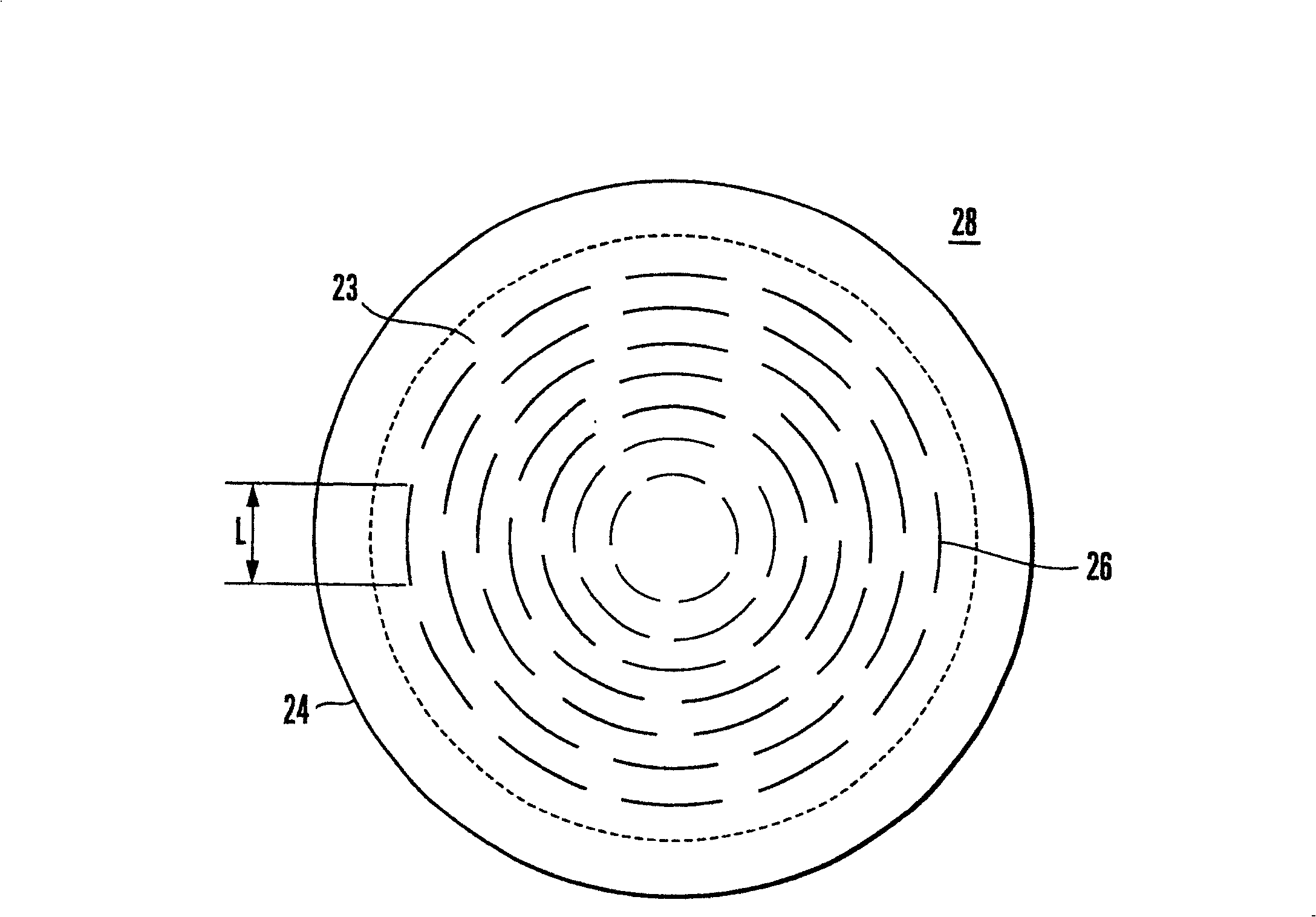
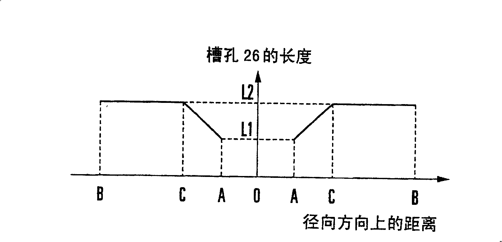
[0064] Attach the reference Figure 5A and 5B A plasma processing apparatus according to a second embodiment of the present invention is described. Figure 5A is a plan view showing the layout of the RLSA antenna surface used in this embodiment; Figure 5B is a graph showing the variation in slot length with respect to the radial direction. exist Figure 5A and 5B in, with Figure 2A and 2B The same or similar parts are denoted by the same reference numerals, and descriptions thereof will be omitted as appropriate. Figure 5A corresponds to Figure 2A .

[0065] As shown in FIG. 5 , it is assumed that a predetermined position on the path from the first middle portion C to the peripheral portion B of the antenna surface 128 (hereinafter will be referred to as a second middle portion) is denoted by D. As shown in FIG. In the radial direction of the antenna surface 128, the length L of the slot 126 increases monotonically from a length L1 at the central portion A, reaching...


PUM


Abstract

The length (L) of a slot ( 26 ) increases monotonously from the central portion (A) of an antenna surface ( 28 ) in the radial direction, and reaches the maximal value at the first intermediate portion (C). The maximal value is maintained from the first intermediate portion (C) until the peripheral portion (B). When compared to a case wherein the length of the slot is increased monotonously from the central portion of the antenna surface ( 28 ) until its peripheral portion, the power radiated from a slot antenna can increase. Accordingly, the power which is not radiated from the slot antenna but remains in it decreases, so that the reflected power from the slot antenna decreases.

Description

technical field [0001] The present invention relates to a plasma processing apparatus and a plasma generating method, and more particularly, to a plasma processing apparatus and a plasma generating method for generating plasma by supplying an electromagnetic field into a processing container using a slot antenna. Background technique [0002] In the manufacturing process of semiconductor devices or flat panel displays, plasma processing equipment is often used to perform processes such as formation of oxide films, crystal growth of semiconductor layers, etching and ashing. Among plasma processing apparatuses, a high-frequency plasma processing apparatus is effective, which supplies a high-frequency electromagnetic field into a processing container and ionizes and separates gas in the processing container by the effect of the electromagnetic field, thereby generating plasma. Since high-frequency plasma processing equipment can generate low-pressure, high-density plasma, it ca...

Claims


Application Information

Patent Timeline
Patent Type & Authority Patents(China)
IPC IPC(8): H01L21/3065H01L21/302H05H1/46H01J37/32
CPCH01J37/3222H01J37/32192H05H1/26
Inventor 石井信雄八坂保能高桥应明安藤真
Owner TOKYO ELECTRON LTD
Why Eureka
Try Eureka