Wind turbine blade

a technology of wind turbine blades and blades, which is applied in the direction of liquid fuel engines, vessel construction, marine propulsion, etc., can solve the problems of high fatigue load, high fatigue load, and high fatigue load, and achieve the effect of minimizing fatigue and extreme blade load

Active Publication Date: 2011-12-27
GAMESA INNOVATION & TECH SA
View PDF9 Cites 13 Cited by
  • Summary
  • Abstract
  • Description
  • Claims
  • Application Information

AI Technical Summary

Benefits of technology

[0009]An object of the present invention is to provide a wind turbine blade minimizing the fatigue and extreme blade loads, particularly at the mid-span section of the blade.
[0010]Another object of the present invention is to provide a wind turbine blade that allows minimizing the fatigue and extreme blade loads in other components of the wind turbine.
[0012]In a preferred embodiment said modified zone is located along a section of the blade extending between 20%-50% of its length measured from its tip. Hereby a blade that allows reducing the fatigue and extreme loads is achieved without the need of extending said modification along the whole length of the blade.
[0013]In another preferred embodiment said modified zone is done attaching a device such as a stall strip to the blade. Hereby a blade that allows reducing the fatigue and extreme loads is achieved by means of an inexpensive device which can be easily attached to the blade, whether during its manufacturing or afterwards.
[0014]In another preferred embodiment said modified zone is done attaching or inserting into the blade a deformable device and actuator means for providing the shape and size changes in it. Hereby a blade that allows reducing the fatigue and extreme loads by means of an active controlled device is achieved.

Problems solved by technology

A current challenge in the wind turbine industry is providing a blade design minimizing the fatigue and extreme loads and, consequently, allowing the reduction of the material, weight and prize of the blade.
A high standard deviation of lift and drag means that the variation of the aerodynamic loads is high resulting in higher fatigue loads.
In these situations it may happen that the root section of the blade has positive lift and the tip section has negative lift causing high fatigue loads, specially at the mid-span section of the blade.
In that case, negative lift is desired in the blades, but very large negative lift during the transition period could lead to large loads in the blades or any other component in the wind turbine.
Another situation where high fatigue loads are encountered is during the pitch variation introduced to minimise the effect of gusts and big scale atmospheric turbulence.

Method used


Image

  • Wind turbine blade
  • Wind turbine blade
  • Wind turbine blade

Examples


Embodiment Construction

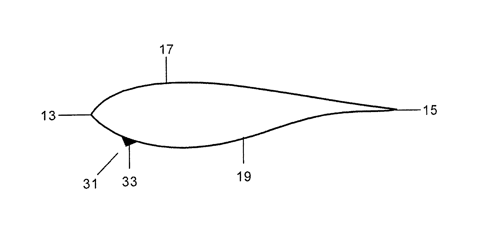
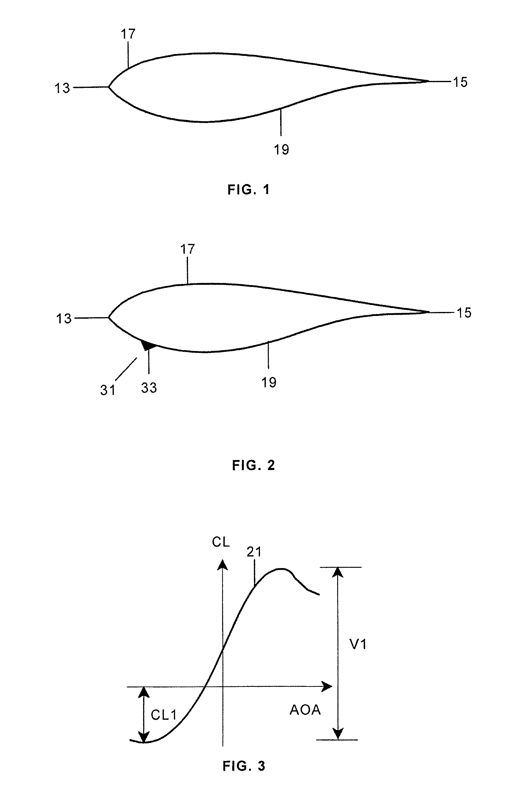
[0022]In traditional profile design of wind turbine blades the aim is to get the best performance of the profiles as possible which is often understood as having high lift and low drag.

[0023]A typical wind turbine blade 11 has generally a flow-optimized profile such as the profile shown in FIG. 1 having a leading edge 13, a trailing edge 15 and a lifting surface with a suction side 17 and a pressure side 19.

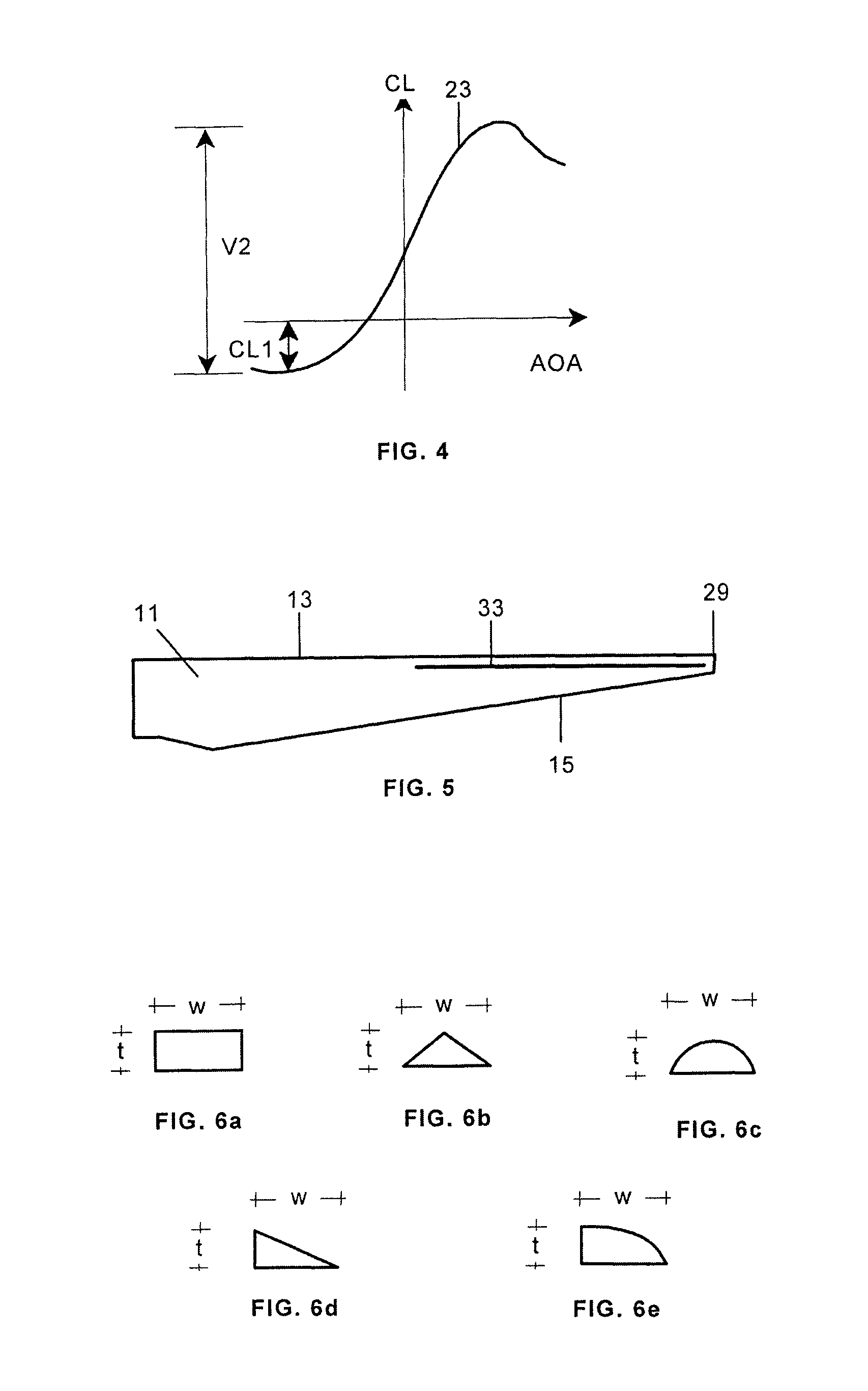
[0024]FIG. 3 shows a lift coefficient CL versus angle of attack AOA typical curve 21 for that type of profiles. These curves have a maximum and a minimum values for CL, being the maximum associated to positive lift and the minimum to negative lift and there is therefore a significant variation V1 between maximum positive lift and maximum negative lift.

[0025]According to the present invention the high fatigue loads appearing in those situations in which the outer section of the blade has a negative lift and suddenly changes to a positive lift or vice versa, especially due to turbu...


PUM


Abstract

A wind turbine blade (11) having an aerodynamic profile with a leading edge (13), a trailing edge (15) and suction and pressure sides (17, 19) between the leading edge (13) and the trailing edge (15), wherein the pressure side (19) includes a modified zone (31) shaped for reducing the negative lift coefficient which is done whether attaching a device (33) such as a stall strip to the blade (11) or attaching or inserting into the blade (11) a deformable device and actuator means for providing the shape and size changes in it.

Description

FIELD OF THE INVENTION[0001]The invention relates to wind turbine blades that minimize the fatigue and extreme loads and more in particular to wind turbine blades that minimize the fatigue and extreme loads in the mid-span section of the blade.BACKGROUND[0002]A current challenge in the wind turbine industry is providing a blade design minimizing the fatigue and extreme loads and, consequently, allowing the reduction of the material, weight and prize of the blade.[0003]The airfoil sections on the wind turbine blades in normal production operate at angles of attack ranging from low angles of attack, where the lift is low on the linear part of the lift versus angle of attack curve, to high angles of attack where the airfoil section is just before stall or in stall.[0004]The variation of the aerodynamic loads can be measured as the oscillations of the aerodynamic lift and drag. The standard deviation statistic of a data set or time series is often used as a good indicator of the oscilla...

Claims


Application Information

Patent Timeline
Patent Type & Authority Patents(United States)
IPC IPC(8): F01D5/18
CPCF03D1/0641F05B2240/122F05B2240/301F05B2250/70Y02E10/721Y02E10/72F05B2240/3062F03D1/0608F03D7/022
Inventor GARCILLAN RUEDA, LUIS MIGUELFRIEDRICH, MICHAELGOMEZ DE LAS HERAS CARBONELL, ENRIQUE
Owner GAMESA INNOVATION & TECH SA
Why Eureka
Try Eureka