Head-mounted virtual display apparatus with a near-eye light deflecting element in the peripheral field of view

a virtual display and peripheral field technology, applied in the direction of instruments, spectacles/goggles, non-optical parts, etc., can solve the problems of occlusion of a portion of the forward fov, its suitability primarily, and increase the complexity of construction, so as to prevent slippage and/or dislodging of the head-mounted support

Inactive Publication Date: 2004-08-03
GEIST RICHARD
View PDF2 Cites 127 Cited by
  • Summary
  • Abstract
  • Description
  • Claims
  • Application Information

AI Technical Summary

Benefits of technology

A still further feature of the invention resides in the use of active and passive alignment means, including moveable connections, extended LDEs and image warping electronics, to minimize or eliminate geometric distortion due to tilting of the observable virtual image plane.
A still further feature of the present invention resides in the use of distinct assemblies for the illumination source, near-eye optic, (adjacent and non-adjacent) folding optics and any additional optics (thus providing modular construction capability).
Image placement refers to changing the apparent distance from the eye of a focused observable virtual image. Image placement plays a key role in minimizing eye (muscle) fatigue and possible user discomfort during extended periods of HMD use. The standard approach to reducing eye fatigue is to place the virtual (or apparent) image at an apparent (or perceived) distance comparable to that of the primary objects in the user's forward FOV in order to minimize accommodation when the eye switches back and forth between the virtual image and the primary objects. For example, rather than having the virtual image at a standard reading distance of 250 mm, a person working at a computer may wish to perceive the image at a workstation distance of 600 mm to minimize the need for accommodation by the eye when switching between the real image of the computer screen and the inset virtual image of the present invention. This may be accomplished by either fixing the apparent distance based on the primary task of the wearer or by including an adjustment to allow the user to change the apparent distance according to the task at hand.
It will be further understood by one of ordinary skill in the art that standard techniques for minimizing glare and washout from external and internal sources of illumination, such as anti-reflective coatings, opaque coatings, opaque baffling, opaque housings, etc., may be required.
It will be still further understood by one of ordinary skill in the art that a supplemental means of securing the apparatus to the head--such as an adjustable strap or elastic headband--may be used to help prevent against slippage and / or dislodging of the head-mounted support during user motion and activity.

Problems solved by technology

The disadvantages of a boom style HMD include a physical boundary that extends a distance from the face, occlusion of a portion of the forward FOV, and its suitability primarily for stationary activities due to vibration of the cantilever arm during user motion.
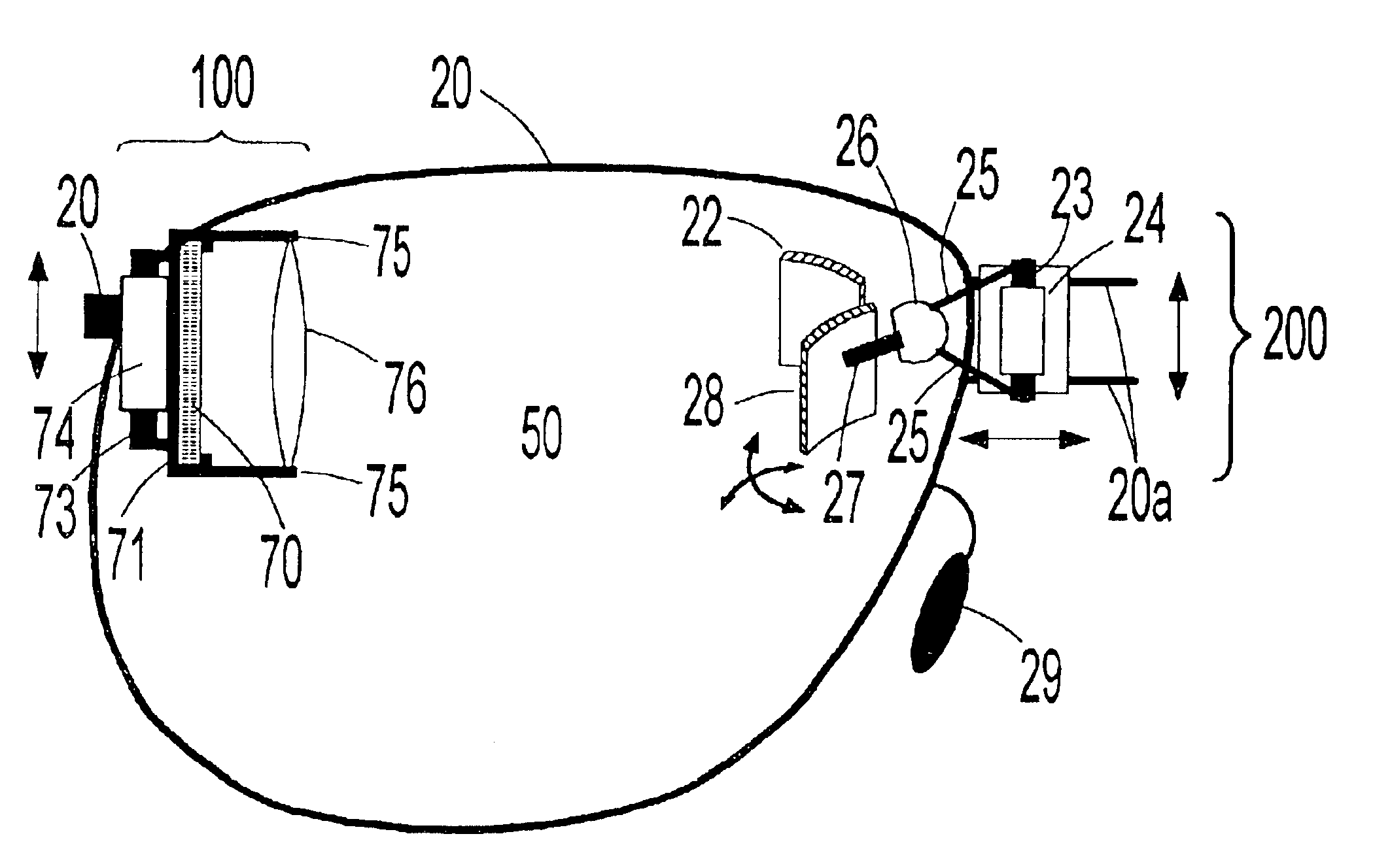
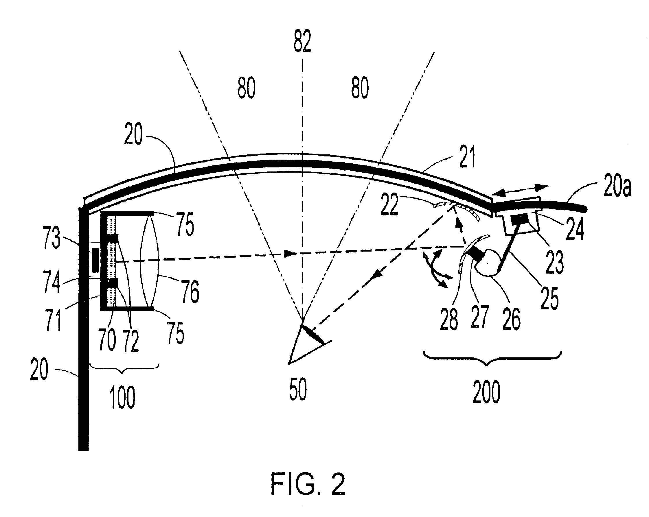
The compact nature of a glasses-mounted display (GMD), however, generally requires a folding of the optical train, which increases the complexity of the construction.
Off-axis optical configurations allow more compact constructions but suffer from higher levels of aberrations.
Taking user comfort into account, the former requirement is best satisfied by a support frame in contact with both ears and the bridge of the nose; while the latter requirement negates the use of a relatively long, thin cantilever arm as the support structure for attaching the eyepiece to the frame, since this type of structure is susceptible to vibration during user motion.
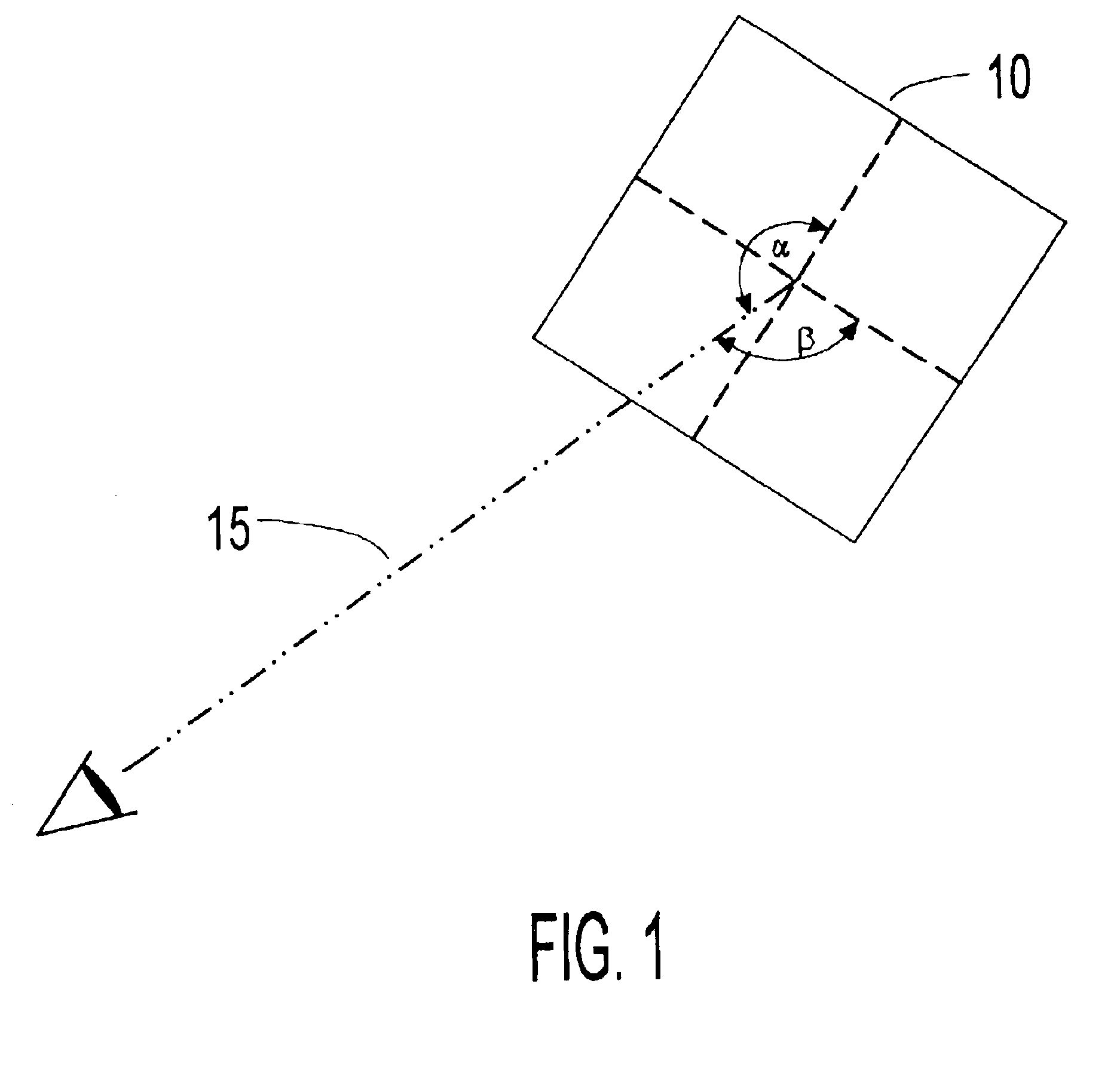
In general, geometric distortion represents the inability of the system to correctly map the shape of the object into image space (i.e., geometrical distortion represent mapping errors).
Keystone distortion arises in off-axis projection systems and in optical systems when the optical axis of a powered optic is not perpendicular to the plane of the object (e.g., when the magnifying stage is tilted with respect to the display or vice versa).
Keystone distortion is inherent in most off-axis HMD optical configurations, as are some higher-order, asymmetric types of geometric distortion.
A number of boom-style or cantilever arm type HMDs have appeared in the prior art that do not obscure normal forward vision (such as U.S. Pat. No. 4,869,575 disclosed by Kubik) but are not suitable for mobile activities due to vibration of the cantilever arm during user motion.
In addition a common disadvantage of this type of HMD is the inability to moveably and independently adjust the near-eye LDE (also commonly referred to herein as the near-eye optic).
However, no alignment means-are provided to establish one- or two-dimensional orthogonality (or more commonly referred to herein simply as orthogonality) for different users.
However, none of these inventions provide the alignment means necessary to orthogonally align the observable virtual image plane for different users when the near-eye optic is located in the peripheral FOV and normal forward vision is completely unobscured.
Furness et. al. does not, however, provide the second alignment means necessary to establish orthogonality.
The alignment means provided by Heacock et. al, however, are insufficient to establish orthogonality for different users since the display and eyepiece are not both simultaneously adjustable (i.e., the display is fixed in place while the eyepiece is adjustable).
Bettinger does not provide the moveable connections necessary to orthogonally align the observable VIP for different users.
In addition, Bettinger does not allow modification of the conventional spectacle frame form.
Furthermore, Bettinger does not allow the near-eye LDE to be a flat mirror or allow the curvature of the near-eye LDE to be readily varied, since the construction is limited to standard lens curvatures.
Spitzer does not provide means for articulating the near-eye LDE (or an adjacent LDE) as is necessary to orthogonally align the observable VIP for different users.
In addition, Spitzer does not allow the optical pathway to be entirely external of the lens, nor allow the near-eye LDE to be independent of and non-integral with the lens.
In addition, Holakovszky et al. does not provide the alignment means necessary to orthogonally align the observable VIP for different users when the near-eye optics are located the normal peripheral FOV.
Thus, Holakovszky et al. cannot provide the unobstructed forward vision required for use during mobile activities.
Wells et. al. does not provide the alignment means necessary to locate the near-eye optics in the normal peripheral F
Even a small tilt angle, on the order of five degrees, leads to a noticeable level of geometric distortion.
Additional alignment means, however, may be required if elements involved in the establishment of the adjunct optical planes cannot be readily fixed in place without giving rise to additional sources of geometric distortion.
The disadvantage of a single LDO embodiment is that the near-eye optic cannot normally be kept parallel to the spectacle plane, thus resulting in a less compact form factor.

Method used


Image

  • Head-mounted virtual display apparatus with a near-eye light deflecting element in the peripheral field of view
  • Head-mounted virtual display apparatus with a near-eye light deflecting element in the peripheral field of view
  • Head-mounted virtual display apparatus with a near-eye light deflecting element in the peripheral field of view

Examples


Embodiment Construction

glasses-mounted VDA is constructed by adding two non-detachable assemblies--for an adjacent folding optic and a microdisplay (Planar AMEL 640.times.480 monochrome microdisplay)--to a metal spectacle frame (Limited Editions: Style SST 20; Size 57 / 18 145). The first alignment means consists of an extended near-eye optic and (stick-friction) translational motion mechanisms (TMMs) integrated into the image source and adjacent folding optic assemblies. A hinge for small angle rotation of the display is incorporated into the image source assembly as a part of the second alignment means. A stick-friction sliding mechanism, incorporated into the attachment and connection between the bridge crosspieces and the adjacent folding optic support bracket, provides an adjustable and controllable focusing mechanism. A hinge, incorporated into the attachment and connection between the adjacent folding optic holder and support bracket is another component of the second alignment means.

Two 20 mm pieces...


PUM


Abstract

The present invention is a head-mounted virtual display apparatus based on a cross-cavity optical configuration, in which a near-eye light deflecting element (LDE) is located in the peripheral field of view. Positioning of the near-eye LDE in the peripheral field of view provides the user simultaneously with "look toward" access to an inset magnified image of a miniature display and an unobstructed forward field of view of at least 35 degrees. Active and passive alignment means, including articulating connections and image warping electronics, allow correction of geometric distortion arising from folding of the optical train and / or embodiments based on off-axis optical configurations.

Description

BACKGROUND OF INVENTIONa) Field of the InventionThe present invention relates to a head-mounted virtual display apparatus (VDA) based on a cross-cavity optical configuration with an unobstructed forward field of view. More particularly, a near-eye light deflecting element (LDE) located in the peripheral field of view provides "look toward" access to an inset magnified image of a miniature display. Active and passive alignment means, including articulating connections and image warping electronics, allow correction of geometric distortion arising from folding of the optical train and / or embodiments based on off-axis optical configurations.b) Description of the Prior ArtThe head-mounted display (HMD) field has evolved on a number of fronts over the past 20 years. The earliest development by the military focused on wide field of view (FOV), see-through helmet-mounted displays for aircraft guidance and weapon aiming applications, in which the virtual image overlies the ambient environme...

Claims


Application Information

Patent Timeline
Patent Type & Authority Patents(United States)
IPC IPC(8): G02B27/01G02B27/00
CPCG02B27/0172G02B27/0176G02B2027/0178G02B2027/0132
Inventor GEIST, RICHARD EDWIN
Owner GEIST RICHARD
Why Eureka
Try Eureka