Head-mounted virtual display apparatus for mobile activities

a virtual display and mobile activity technology, applied in the direction of static indicating devices, operating means/releasing devices of valves, instruments, etc., can solve the problems of occlusion of a portion of forward fov, its suitability primarily, and increase the complexity of construction, so as to prevent slippage

Inactive Publication Date: 2006-12-05
GEIST RICHARD
View PDF1 Cites 79 Cited by
  • Summary
  • Abstract
  • Description
  • Claims
  • Application Information

AI Technical Summary

Benefits of technology

[0033]A still further feature of the invention resides in the use of active and passive alignment means, including moveable connections, extended LDEs and image warping electronics, to minimize or eliminate geometric distortion due to tilting of the observable virtual image plane.
[0035]A still further feature of the present invention resides in the use of distinct assemblies for the illumination source, near-eye optic, (adjacent and non-adjacent) folding optics and any additional optics (thus providing modular construction capability).
[0040]As used herein, the term image warping electronics refers to the software and / or electrical and electronic components required to electronically or computationally predistort the images produced by the illumination source, for the purpose of passively minimizing or eliminating image degrading factors produced by the optical train that are purely geometric in nature. In general, image warping electronics are disposed for orthogonal alignment of the observable virtual image plane with the optical axis in image space between the user's eye the virtual image plane to establish one- or two-dimensional orthogonality; and are integrated into the electrical and electronic means associated with the illumination source.
[0044]Image placement refers to changing the apparent distance from the eye of a focused observable virtual image. Image placement plays a key role in minimizing eye (muscle) fatigue and possible user discomfort during extended periods of HMD use. The standard approach to reducing eye fatigue is to place the virtual (or apparent) image at an apparent (or perceived) distance comparable to that of the primary objects in the user's forward FOV in order to minimize accommodation when the eye switches back and forth between the virtual image and the primary objects. For example, rather than having the virtual image at a standard reading distance of 250 mm, a person working at a computer may wish to perceive the image at a workstation distance of 600 mm to minimize the need for accommodation by the eye when switching between the real image of the computer screen and the inset virtual image of the present invention. This may be accomplished by either fixing the apparent distance based on the primary task of the wearer or by including an adjustment to allow the user to change the apparent distance according to the task at hand.
[0047]It will be further understood by one of ordinary skill in the art that standard techniques for minimizing glare and washout from external and internal sources of illumination, such as anti-reflective coatings, opaque coatings, opaque baffling, opaque housings, etc., may be required.
[0051]It will be still further understood by one of ordinary skill in the art that a supplemental means of securing the apparatus to the head—such as an adjustable strap or elastic headband—may be used to help prevent against slippage and / or dislodging of the head-mounted support during user motion and activity.

Problems solved by technology

The disadvantages of a boom style HMD include a physical boundary that extends a distance from the face, occlusion of a portion of the forward FOV, and its suitability primarily for stationary activities due to vibration of the cantilever arm during user motion.
The compact nature of a glasses-mounted display (GMD), however, generally requires a folding of the optical train, which increases the complexity of the construction.
Off-axis optical configurations allow more compact constructions but typically suffer from higher levels of optical aberrations and geometric distortion.
Taking user comfort into account, the former requirement is best satisfied by a support frame in contact with both ears and the bridge of the nose; while the latter requirement negates the use of a relatively long, thin cantilever arm as the support structure for attaching the eyepiece to the frame, since this type of structure is susceptible to vibration during user motion.
In general, geometric distortion represents the inability of the system to correctly map the shape of the object into image space (i.e., geometrical distortion is representative of a mapping error).
Keystone distortion arises in off-axis projection systems and in optical systems when the optical axis of a powered optical element (or optic) is not perpendicular to the plane of the object (e.g., when the magnifying stage is tilted with respect to the display or vice versa).
Keystone distortion is inherent in most off-axis HMD optical configurations, as are some higher-order, asymmetric types of geometric distortion.
A number of boom-style or cantilever arm type HMDs have appeared in the prior art that do not obscure normal forward vision (such as U.S. Pat. No. 4,869,575 disclosed by Kubik) but are not suitable for mobile activities due to vibration of the cantilever arm during user motion.
In addition a common disadvantage of this type of HMD is the inability to moveably and independently adjust the LDE that redirects the light path towards the user's eye (referred to herein as the near-eye LDE or near-eye optic).
However, none of these inventions provide the alignment means necessary to orthogonally align the observable virtual image plane for different users when the near-eye optic is located in the peripheral FOV and normal forward vision is completely unobscured.
However, no aligment means are provided to establish one- or two-dimensional orthogonality for different users.

Method used


Image

  • Head-mounted virtual display apparatus for mobile activities
  • Head-mounted virtual display apparatus for mobile activities
  • Head-mounted virtual display apparatus for mobile activities

Examples


second embodiment

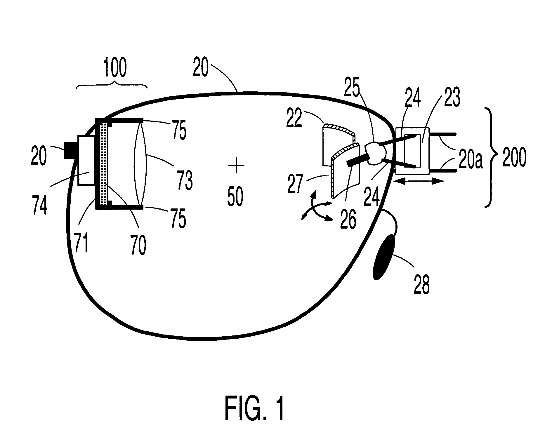
[0095]In the present invention, the near-eye optic receives illumination indirectly from the magnifying stage via a single light-deflecting element, termed an adjacent folding optic (AFO) herein. More specifically, the magnifying stage is disposed for simultaneous illumination reception from the real image source for first intermediate (real or virtual) image formation and illumination transmission to the adjacent folding optic. The adjacent folding optic is disposed for simultaneous illumination reception from the magnifying stage for second intermediate (real or virtual) image formation and illumination redirection to the near-eye optic. The near-eye optic is disposed for simultaneous illumination reception from the adjacent folding optic for observable virtual image formation and illumination redirection to the user's eye. In this embodiment, the first alignment means may be either a passive alignment means or an active alignment means; and the second alignment means may be eithe...

third embodiment

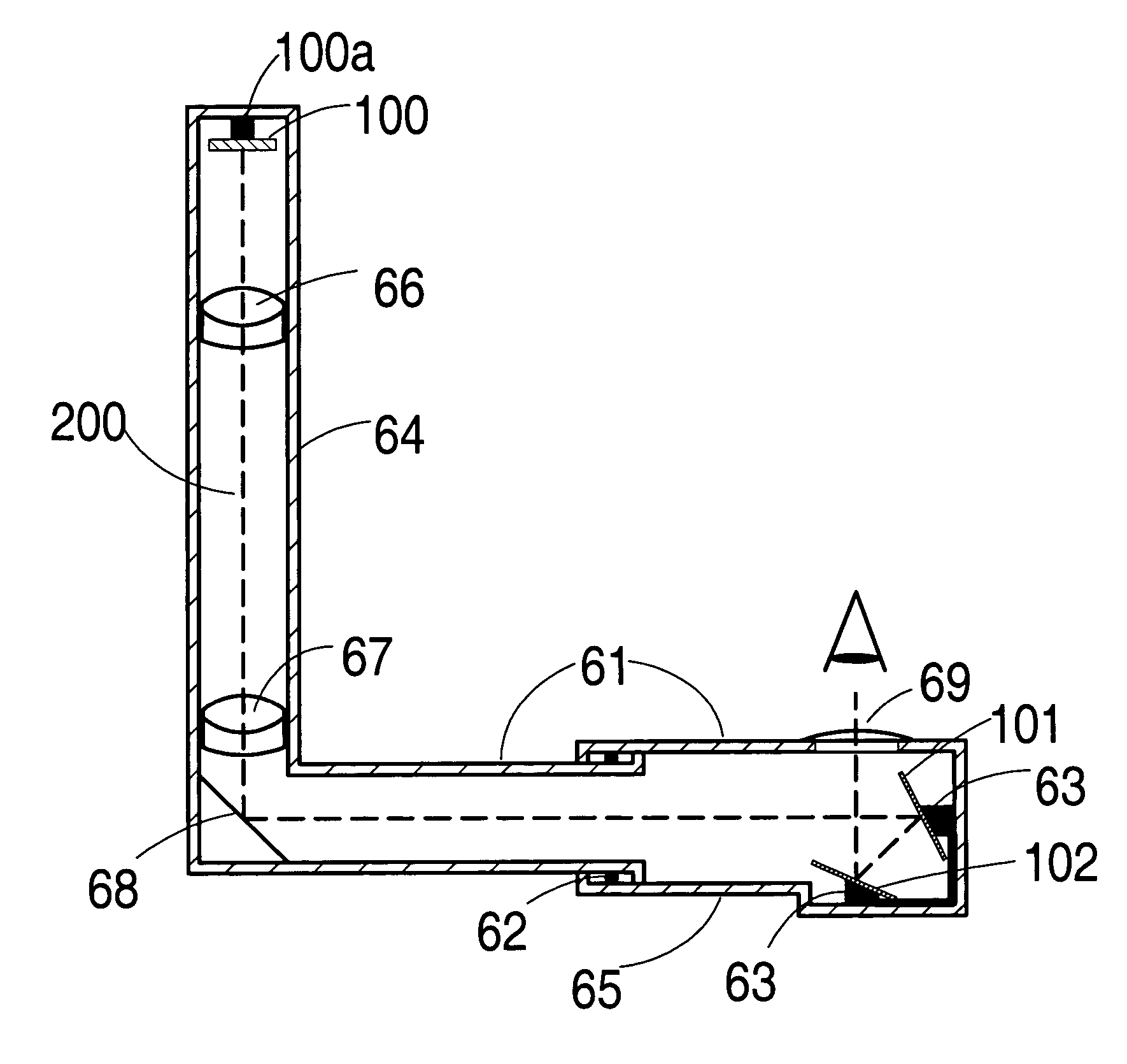
[0111]In the present invention, the near-eye optic receives illumination indirectly from magnifying stage via a pair of light-deflecting elements. The light deflecting folding optic nearest the magnifying stage is termed the non-adjacent folding optic. The light deflecting folding optic nearest the near-eye optic is termed the adjacent folding optic. More specifically, the magnifying stage is disposed for simultaneous illumination reception from the real image source for first intermediate (real or virtual) image formation and illumination transmission to the non-adjacent folding optic. The non-adjacent folding optic is disposed for simultaneous illumination reception from the magnifying stage for second intermediate (real or virtual) image formation and illumination redirection to the adjacent folding optic. The adjacent folding optic is disposed for simultaneous illumination reception from the non-adjacent folding optic for third intermediate (real or virtual) image formation and ...


PUM


Abstract

The present invention is a head-mounted virtual display apparatus based on a non-cross-cavity optical configuration, in which a near-eye light deflecting element (LDE) is located in the peripheral field of view. Positioning of the near-eye LDE in the peripheral field of view provides the user with simultaneous access to an inset magnified image of a miniature display and an unobstructed forward field of view of at least 35 degrees. Active and passive alignment means, including articulating connections and image warping electronics, allows for correction of geometric distortion arising from folding of the optical train, and orthogonal alignment of the virtual image plane with the optical axis between the user's eye and the virtual image plane.

Description

CROSS REFERENCE TO RELATED APPLICATIONS[0001]This application is a continuation-in-part of U.S. patent application Ser. No. 10 / 216,958, filed Aug. 12, 2002 now abandoned.BACKGROUND OF INVENTION[0002]a) Field of the Invention[0003]The present invention relates to a virtual display apparatus (VDA), with a light deflecting near-eye optic located in the peripheral field of view, for presenting to the eye a magnified virtual image of a miniature display when the viewer's gaze is directed towards the periphery. More particularly, the present invention relates to a head-mounted virtual display apparatus based on a non-cross-cavity optical configuration where a grouping of one, two or three light deflecting elements (IDEs) combine to redirect the light path from a miniature display towards the eye to provide “look toward” access to an inset virtual image, while simultaneously providing unobstructed forward vision. Active and passive alignment means, such as articulating connections and imag...

Claims


Application Information

Patent Timeline
Patent Type & Authority Patents(United States)
IPC IPC(8): G02B27/14F16K25/00F16K31/12G09G5/00G02B27/00G02B27/01
CPCG02B27/0172G02B2027/011G02B2027/0132G02B2027/0178
Inventor GEIST, RICHARD EDWIN
Owner GEIST RICHARD
Why Eureka
Try Eureka