Single drive variable azimuth and beam tilt antenna for wireless network

a single drive, beam tilt technology, applied in the direction of individual energised antenna arrays, mechanical devices, gearing, etc., can solve the problems of increasing the weight and wind load of the newly installed antenna array, adding substantial weight, size and complexity to the antenna assembly,

Active Publication Date: 2011-12-27
INTEL CORP
View PDF16 Cites 32 Cited by
  • Summary
  • Abstract
  • Description
  • Claims
  • Application Information

AI Technical Summary

Problems solved by technology

This prior art method antenna has a number of disadvantages due to high cost involved in implementing individual phase shifters.
Such highly functional antenna arrays are typically retrofitted in place of simpler, lighter and less functional antenna arrays while weight and wind loading of the newly installed antenna array can not be significantly increased.
Generally, to provide above mentioned functionality remote actuators utilize electromechanical control systems which may add substantial weight, size and complexity to an antenna assembly.

Method used


Image

  • Single drive variable azimuth and beam tilt antenna for wireless network
  • Single drive variable azimuth and beam tilt antenna for wireless network
  • Single drive variable azimuth and beam tilt antenna for wireless network

Examples


case 28

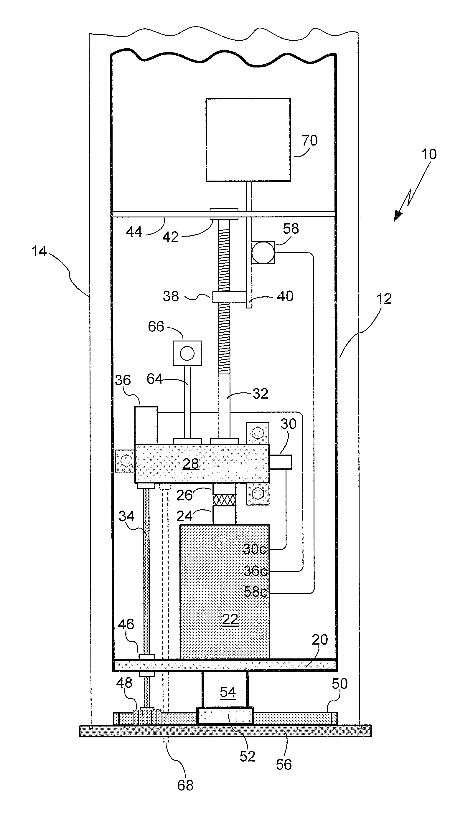
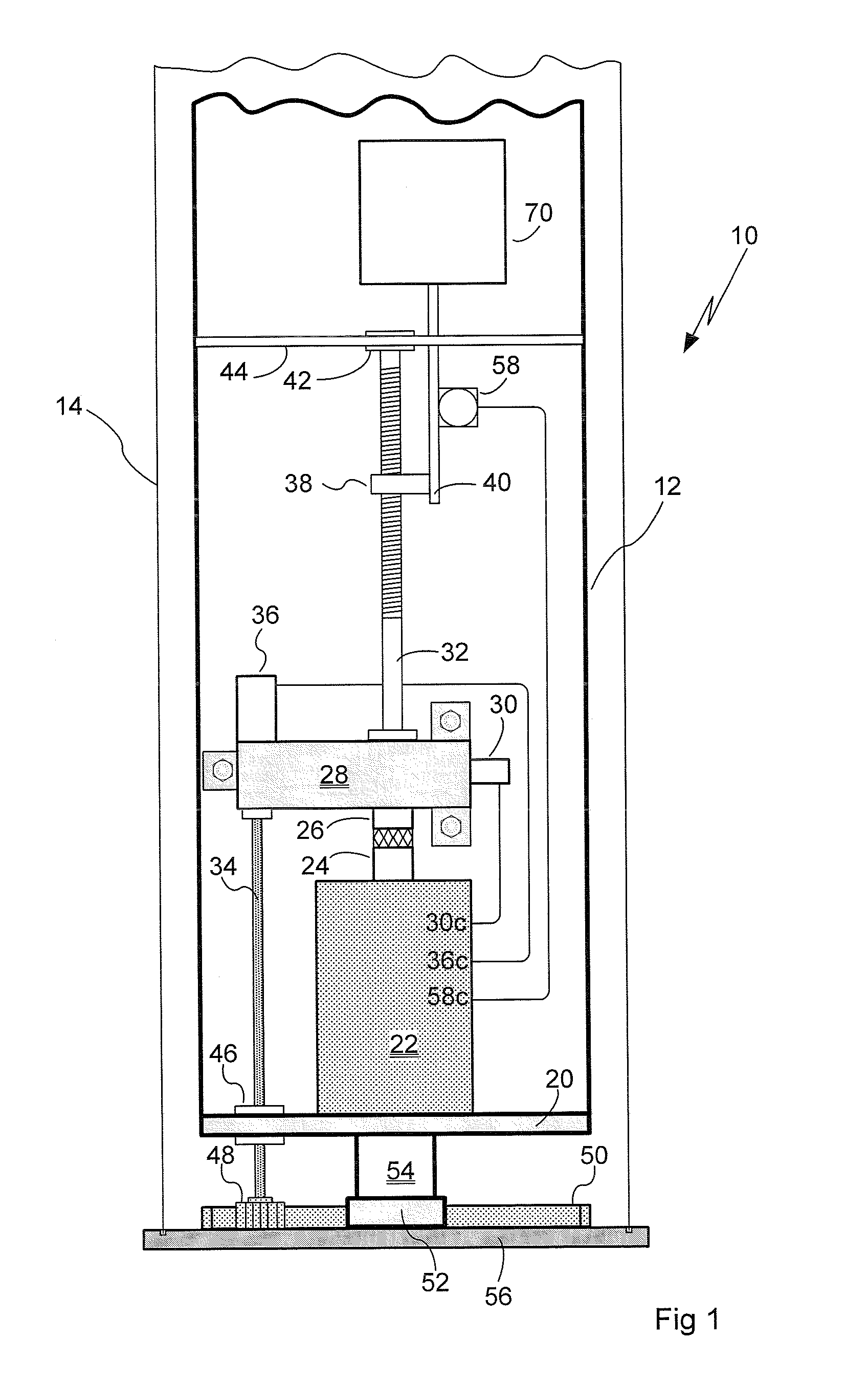
[0031]Transfer case 28 is used to redirect MCM 22 motor output to selectively provide dimensional displacement where needed. In an exemplary non limiting embodiment, transfer case 28, under one control mode, may be configured to drive a jack screw 32 used to control RET phase shifter 70 (details are provided in the above noted WO96 / 37922 and WO02 / 35651 published applications and '303 patent incorporated by reference herein; additional mechanical phase shifter implementations are known to those skilled in the art). If so required, actuating solenoid 30 under MCM control 30c operating in another control mode, is used to redirect MCM 22 motor output to provide rotational drive to azimuth rotator shaft 34. Since MCM motor output may have limited torque capabilities on its own gear reduction can be used within transfer case 28 to provide torque multiplication and speed reduction. In addition to torque multiplication and speed reduction transfer case 28 may incorporate lockouts or parking...


PUM


Abstract

An antenna array employing a combined azimuth and elevation beam angle adjustment electromechanical system is disclosed. The system employs a dual purpose remotely controllable actuator. The actuator is used to adjust azimuth angle of the antenna array and radiation beam tilt of the same. An antenna array employing a combined azimuth, beamwidth and elevation beam angle adjustment electromechanical system is also disclosed.

Description

RELATED APPLICATION INFORMATION[0001]The present application claims priority under 35 USC section 119(e) to U.S. Provisional Patent Application Ser. No. 61 / 004,242, filed Nov. 26, 2007, the disclosure of which is herein incorporated by reference in its entirety.BACKGROUND OF THE INVENTION[0002]1. Field of the Invention[0003]The present invention relates in general to communication systems and components. More particularly the present invention is directed to antennas and antenna arrays employed in wireless communications systems.[0004]2. Description of the Prior Art and Related Background Information[0005]Modern wireless antenna implementations generally include a plurality of radiating elements that may be arranged over a ground plane defining a radiated (and received) signal beamwidth and azimuth angle relative to a defined bore sight. The azimuth radiation pattern of the antenna (in horizontal plane) can be advantageously moved to provide different geographic coverage by rotating...

Claims


Application Information

Patent Timeline
Patent Type & Authority Patents(United States)
IPC IPC(8): H01Q13/10H01Q3/10
CPCH01Q1/246H01Q3/04H01Q3/32H01Q21/08H01Q3/18F16H1/227
Inventor YANG, CHING-SHUNTEJOMURTHI, KOMMANARABINOVICH, ALEXANDER
Owner INTEL CORP
Why Eureka
Try Eureka