Mechanism for folding, sweeping, and locking vehicle wings about a single pivot

a technology for vehicle wings and wings, applied in aircrafts, transportation and packaging, weapons, etc., can solve the problems of concentric shafts affecting the flight of aircraft, and relatively complex operation and manufacturing, and may lack structural integrity of flexible membranes or be perceived as lacking structural integrity

Active Publication Date: 2012-01-03
HARRIS CORP
View PDF8 Cites 99 Cited by
  • Summary
  • Abstract
  • Description
  • Claims
  • Application Information

AI Technical Summary

Problems solved by technology

The asymmetric nature of deploying an oblique wing in flight introduces aerodynamic imbalances that may be problematic for flight control during wing extension.
The concentric shafts penetrate the fuselage and are relatively complex to operate and manufacture.
Such a flexible membrane may lack structural integrity or be perceived to lack structural integrity, as compared with rigid wings.

Method used


Image

  • Mechanism for folding, sweeping, and locking vehicle wings about a single pivot
  • Mechanism for folding, sweeping, and locking vehicle wings about a single pivot
  • Mechanism for folding, sweeping, and locking vehicle wings about a single pivot

Examples


Embodiment Construction

[0018]Although the invention is illustrated and described herein with reference to specific embodiments, the invention is not intended to be limited to the details shown. Rather, various modifications may be made in the details within the scope and range of equivalents of the claims and without departing from the invention.

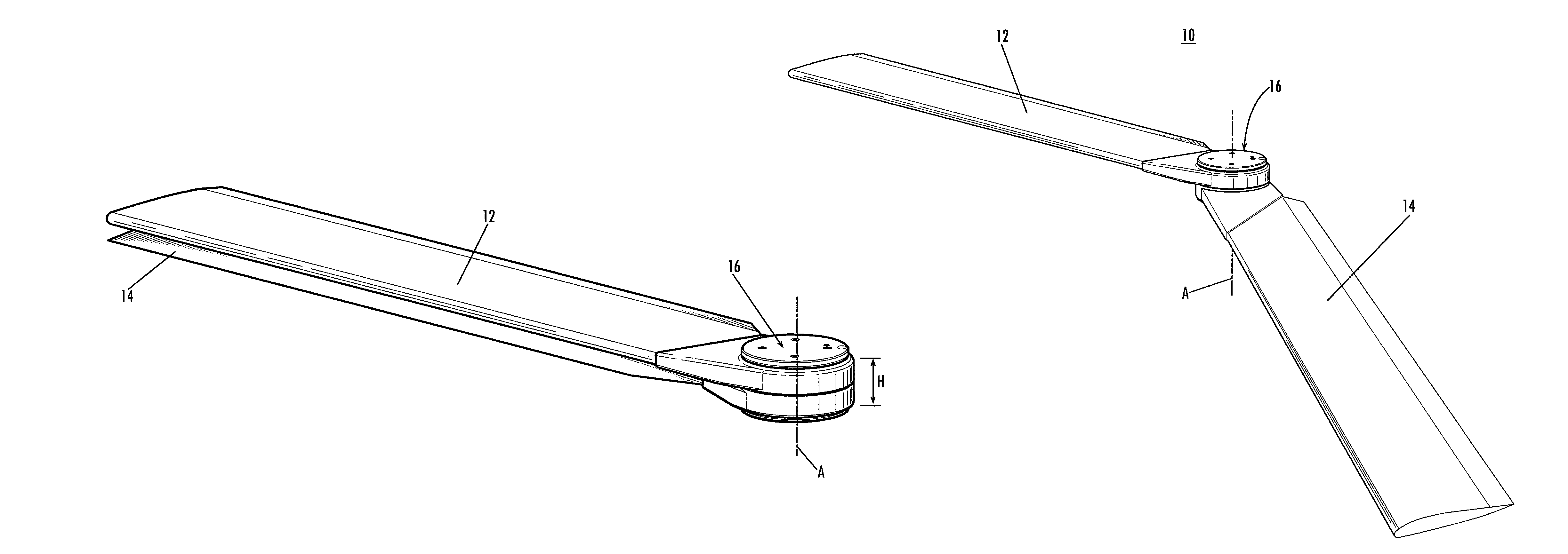
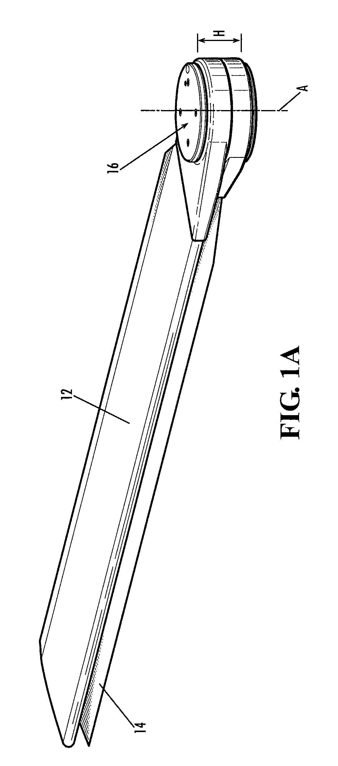
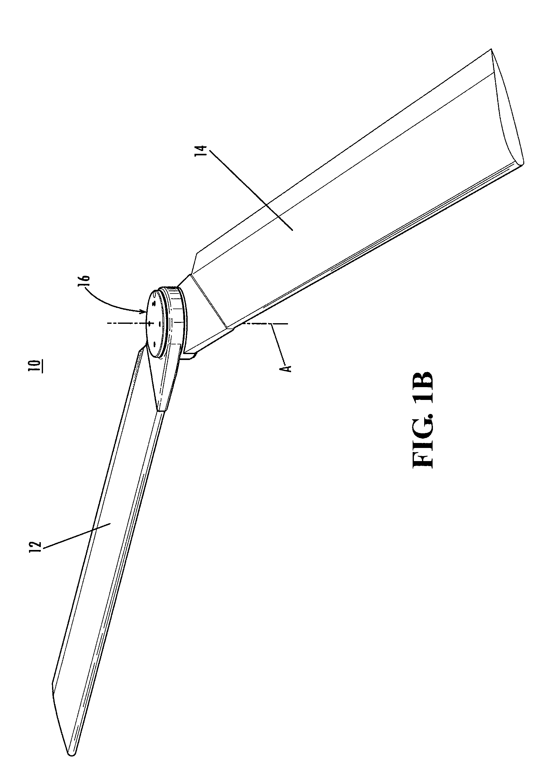
[0019]FIGS. 1A and 1B depict top, front and right side perspective views of a pivoting wing assembly, wherein the pivoting wing assembly is depicted in a stowed configuration in FIG. 1A and the pivoting wing assembly is depicted in a deployed configuration in FIG. 1B. In the figures the pivoting wing assembly is denoted by the numeral ‘10,’ and may be referred to hereinafter as wing assembly 10 or assembly 10. The wing assembly 10 incorporates an all-in-one release, timing and lock assembly and these functions, as opposed to conventional wing assemblies, occupy no additional internal fuselage volume of a vehicle.

[0020]The wing assembly 10 generally includes a firs...


PUM


Abstract

A wing pivot mechanism that is configured to pivot two wings about a single pivot axis of a vehicle, such as an aircraft. The wing pivot mechanism includes a hub, a set of gears positioned at least partially within an interior region of the hub, and two wings that are rotatably connected to the hub. Each wings includes a gear surface extending therefrom. Each gear of the hub assembly engages a gear of a respective wing such that rotation of the gears of the hub assembly causes rotation of the gears of the wings and pivoting of the wings about the single pivot axis in opposite rotational directions between a stowed position and a deployed position. A releasable locking mechanism is provided for locking the wings in a fixed rotational position in both the deployed position and the stowed position.

Description

TECHNICAL FIELD[0001]The present invention relates to a mechanism for pivoting the wings of a vehicle, such as an aircraft, about a single pivot axis.BACKGROUND OF THE INVENTION[0002]A variable-sweep wing is a wing of an aircraft, missile or unmanned vehicle that is capable of being swept back, i.e., rotated with respect to the fuselage of the vehicle, in flight or while stationary. In use, the wing is swept back for storage, carriage, and / or cruising at high speeds; while the wing is unswept for flight operation, specifically at low speeds, takeoff and landing. The variable-sweep wing has been used primarily in military vehicles for performance enhancement and / or storage and carriage considerations.[0003]Several variable-sweep wing configurations are known. In a twin-pivot configuration, the wings of an aircraft pivot about their individual pivot axes. F-14 and F-111 aircrafts incorporate twin-pivot style wings, for example. The aircraft wing beam structure is interrupted by two pi...

Claims


Application Information

Patent Timeline
Patent Type & Authority Patents(United States)
IPC IPC(8): F42B10/00
CPCB64C3/56F42B10/14B64C2201/102B64U30/12
Inventor HAMMERQUIST, ROBERT E.
Owner HARRIS CORP
Why Eureka
Try Eureka