Battery positioning structure for electric vehicle

a positioning structure and electric vehicle technology, applied in the direction of battery/cell propulsion, cell component details, cell components, etc., can solve the problems of troublesome positioning of such a battery unit containing a plurality of battery modules on the vehicle body, and achieve good workability, reduce load, and ensure the effect of positioning reliable and efficien

Active Publication Date: 2012-01-10
MITSUBISHI MOTORS CORP
View PDF117 Cites 35 Cited by
  • Summary
  • Abstract
  • Description
  • Claims
  • Application Information

AI Technical Summary

Benefits of technology

[0017]When positioning the battery system, having a plurality of battery modules, on a vehicle body, the metal bracket attached around the battery modules is fastened to bolts of the vehicle body, and is covered by bands. The bands are fixedly attached to locks. Even when battery modules have different sizes and heights, they can be reliably and efficiently positioned on the vehicle body since size and height differences of the battery modules can be absorbed depending upon where the bands are fastened to the locks.
[0018]According to the invention, the metal bracket is attached on the outer surface of the battery modules at positions where there are no module terminals. Even if crashing energy is applied to the vehicle body, the bracket can reliably hold the battery modules on the vehicle body, do not come into contact with the module terminals, and protect the battery modules against crashing.
[0019]In accordance with the invention, one of check plates is detachably supported by the bracket. The bolts and check plates are aligned. Thereafter, the bracket is attached to the battery modules, and is fixed to the vehicle body with good workability.
[0020]Further, since a plurality of cylindrical parts of the check plates are formed with spaces kept between them, it is possible to reduce load applied to one cylindrical part when crashing energy is applied to the vehicle body. This is effective in reliably positioning the battery units on the vehicle body, and protecting the vehicle against crashing force.
[0021]Still further, a pair of brackets are attached on outer surfaces of a plurality of battery modules, and unite the battery modules. The check plates with cylindrical parts to be attached to bolts of the vehicle body are temporarily attached to the brackets. Even if battery modules have different sizes or heights, they can be reliably and efficiently attached on the vehicle body without applying undue loads to the battery modules.
[0022]The brackets are made of metal sheets, and are shaped not to come into contact with the module terminals. Even if battery module are moved due to crashing energy, the battery system can be reliably kept safe at the time of crashing.

Problems solved by technology

It is very troublesome to position such a battery unit containing a plurality of battery modules on a vehicle body.

Method used


Image

  • Battery positioning structure for electric vehicle
  • Battery positioning structure for electric vehicle
  • Battery positioning structure for electric vehicle

Examples


Embodiment Construction

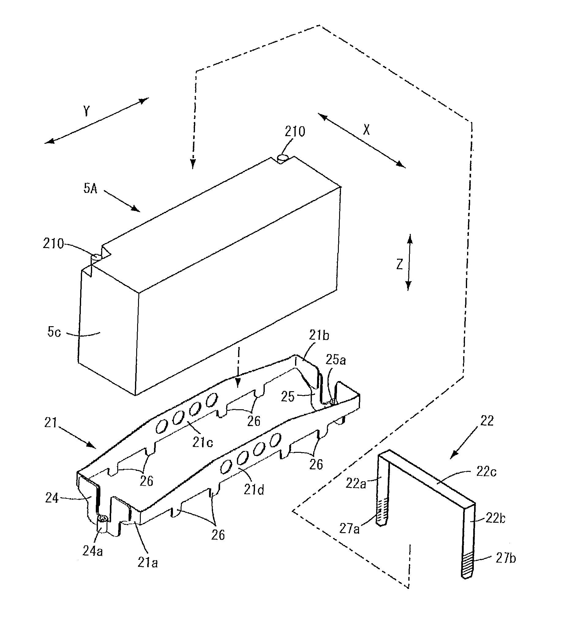
[0050]The battery positioning structure can position battery units with good reliability and workability even when battery modules have different sizes or heights. The battery positioning structure includes a bracket and bands. The battery modules are fitted into the bracket, and are firmly held by the bands which extend across the bracket, and have their opposite ends linked to locks at opposite side edges of the bracket.

Description of Embodiments

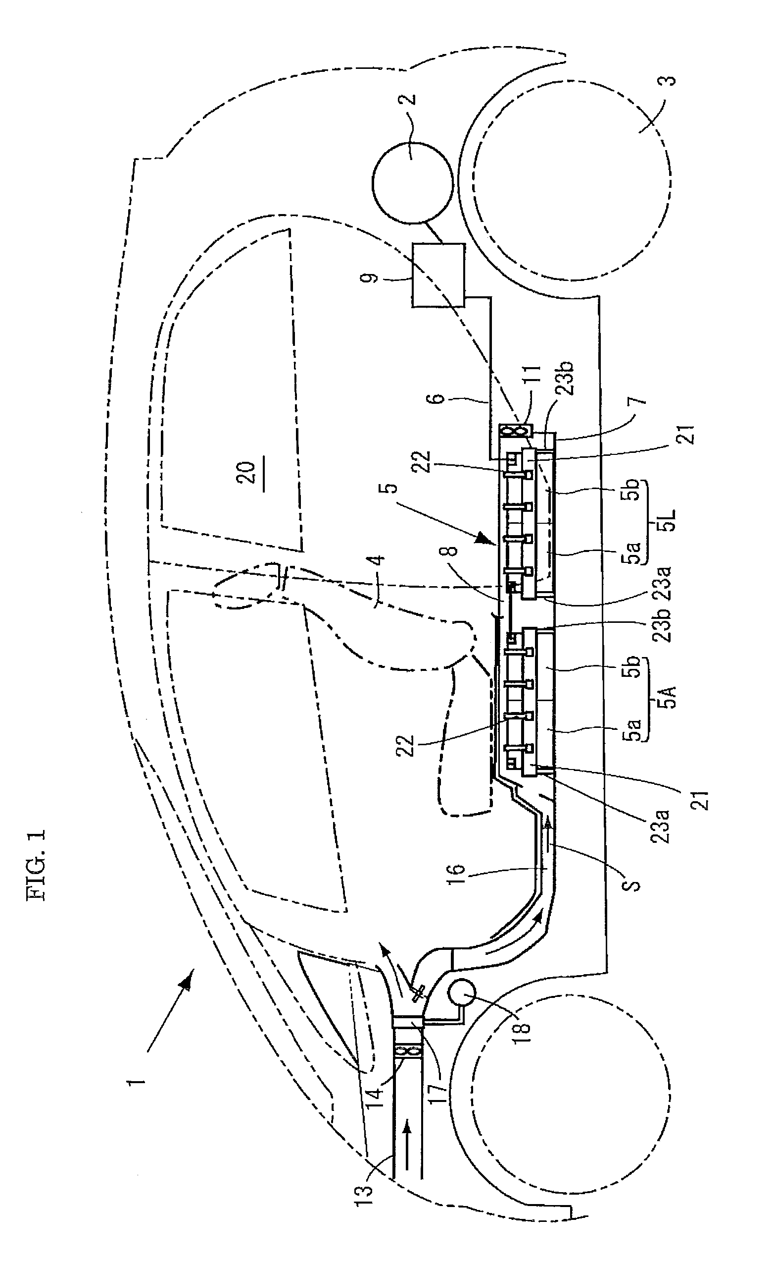
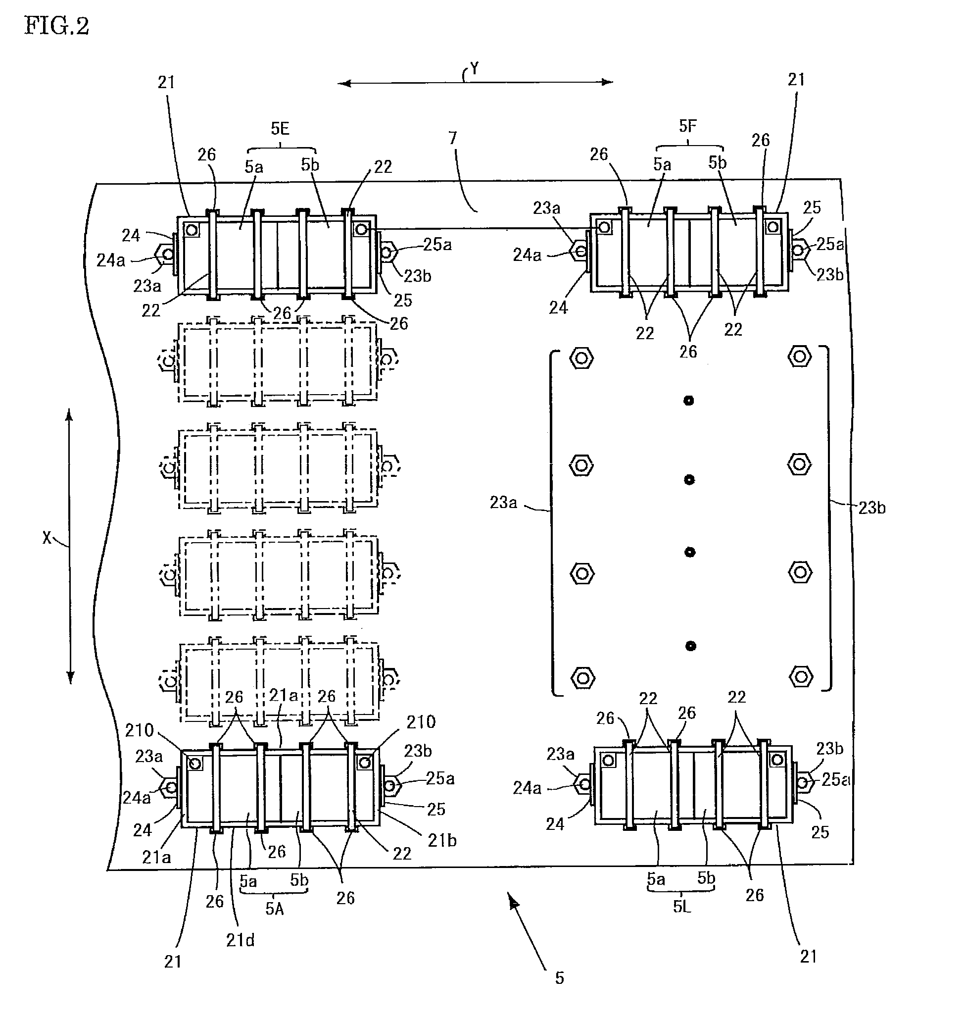
[0051]The invention will be described with reference to embodiments shown in the drawings. Referring to FIG. 1, an electric vehicle 1 is driven by rotating wheels 3 which are rotated by a motor 2. The motor 2 is actuated by power supplied from a battery system 5. The battery system 5 is positioned under seats 4 in an interior of the electric vehicle. The battery system 5 is constituted by a plurality of battery units, each of which includes battery modules. Each battery module is constituted by one battery cell. The battery system 5 is hou...


PUM


Abstract

A battery positioning structure reliably positions battery modules on a vehicle chassis even when battery modules have different sizes and heights. The battery positioning structure includes a bracket having at opposite ends not only check plates which are configured to be positioned on a body of the electric vehicle but also locks at opposite side edges of the bracket, the bracket being configured to be attached to outer surfaces of the battery modules and to unite the battery modules, and bands configured to extend across the bracket, and linked to the locks at opposite ends of the bracket. The battery modules and the bracket are positioned on the body of the electric vehicle.

Description

BACKGROUND OF THE INVENTION[0001]1. Field of the Invention[0002]The present invention relates to a battery positioning structure of an electric vehicle which includes a plurality of battery modules constituted by a plurality of battery cells.[0003]2. Description of the Related Art[0004]Generally, an electric vehicle is provided with a motor as a drive unit and a battery unit as a power source, and is driven by the motor which is actuated by power supplied by the battery unit. A travelling distance of the electric vehicle depends upon performance and capacity of the battery unit. Therefore, the electric vehicle generally includes the battery unit which is constituted by a plurality of battery modules containing rechargeable battery cells. Whenever a battery voltage is decreased, battery cells will be recharged.[0005]It is very troublesome to position such a battery unit containing a plurality of battery modules on a vehicle body. Patent Publication No. 3050010 discloses to fix batter...

Claims


Application Information

Patent Timeline
Patent Type & Authority Patents(United States)
IPC IPC(8): B60R16/04B60L50/64
CPCB60K1/04B60L11/1877H01M2/0247H01M2/1083B60K2001/005B60K2001/0422B60K2001/0433Y02T10/705Y02T10/7005B60K2001/0472B60L50/66Y02T10/70Y02E60/10H01M50/26H01M50/204H01M50/249B60L50/64H01M50/242H01M50/244H01M50/262
Inventor TANEDA, RYOJISUZUKI, HIROYASUTOZUKA, YUJI
Owner MITSUBISHI MOTORS CORP
Why Eureka
Try Eureka