Pivotable table

a technology of pivoting table and hinge, which is applied in the direction of seating arrangement, furniture parts, aircraft crew accommodation, etc., can solve the problems of unison of requirements, unsuitable for absorbing loads, and unsuitable for adjusting the position of the pivoting table, etc., and achieves satisfactory stability and simple handling.

Inactive Publication Date: 2010-05-25
LUFTHANSA TECH AG
View PDF12 Cites 33 Cited by
  • Summary
  • Abstract
  • Description
  • Claims
  • Application Information

AI Technical Summary

Benefits of technology

[0006]The invention is therefore based on the object of providing a table of the type which is mentioned in the introduction, is simple to handle and has satisfactory stability.
[0016]The carrying arm which is provided according to the invention is connected pivotably to the table top in that end region of said carrying arm which is close to the table top. Within the context of the invention, “connected to the table top” includes carrying arms or the supporting arms which are still to be explained being connected to a separate device, such as a carrying frame, which in turn carries the actual table top. The ability to pivot serves to make it possible for the table top to pivot from the substantially perpendicular storage position into the substantially horizontal use position.
[0024]In the storage position, the table top which is stored in the lower housing preferably has an inclination with respect to the perpendicular which preferably lies between 1 and 20°, further lies preferably in the range from 2 to 5°, and particularly preferably lies in the region of approximately 3°. This inclination is preferably configured such that it is oriented in the direction of the passenger seat. It makes it easier for the passenger who is seated next to the lower housing to pull the table top out and permits the installation of the table close to the outer wall of an airplane, even if the external skin is curved inward toward the top. An inclination of this type is of particular significance for the handling capability of the table if the table is installed, for example, on the upper deck of a Boeing 747, as the airplane external skin is inclined inward toward the top in a particularly pronounced manner there.
[0027]The carrying arm can preferably be locked and / or latched in the carrying arm holding position. This brings about reliable holding of the table in the use position. The pivotable connection between the table top and the at least one carrying arm can have at least one angular stop. This annular stop can limit the possible pivoting angle of the table top, with the result that the latter cannot be pivoted beyond the substantially perpendicular position or below the substantially horizontal position. The carrying arm guide in the lower housing preferably has a vertical stop, with the result that the carrying arm cannot be pulled out beyond the upper carrying arm holding position.
[0028]There is frequently a desire for a table, the usable width of which is greater than the height of the lower housing. In this case, a folding table is preferably provided, in which the table top is formed from two or more part tops which can be moved, in particular can be pivoted, between an arrangement, in which they lie on top of one another, and an arrangement, in which they lie next to one another. In the storage position, the part tops can lie in the lower housing in a state, in which they are folded one above another. During the movement into the use position, first of all the part tops which still lie one above another are pulled out and pivoted into the horizontal position, and subsequently the two part tops are moved, in particular pivoted, into their arrangement, in which they lie next to one another. In this embodiment, a carrying frame is preferably arranged only under one part stop. In order to increase the stability of the table overall, there is preferably provision for the carrying frame to have a supporting grip which can be pulled out, is pushed under the second part top in the pulled out position and supports the latter.

Problems solved by technology

It is problematical in tables of this type that a plurality of requirements have to be united which are difficult to combine with one another.
This can be problematical, in particular, in a long lever arm for the active forces (for example, a passenger who stumbles along the aisle).
This solution is disadvantageous, as a lid which is fastened to the credenza by means of a hinge is not particularly well suited for absorbing loads.

Method used


Image

  • Pivotable table
  • Pivotable table
  • Pivotable table

Examples


Embodiment Construction

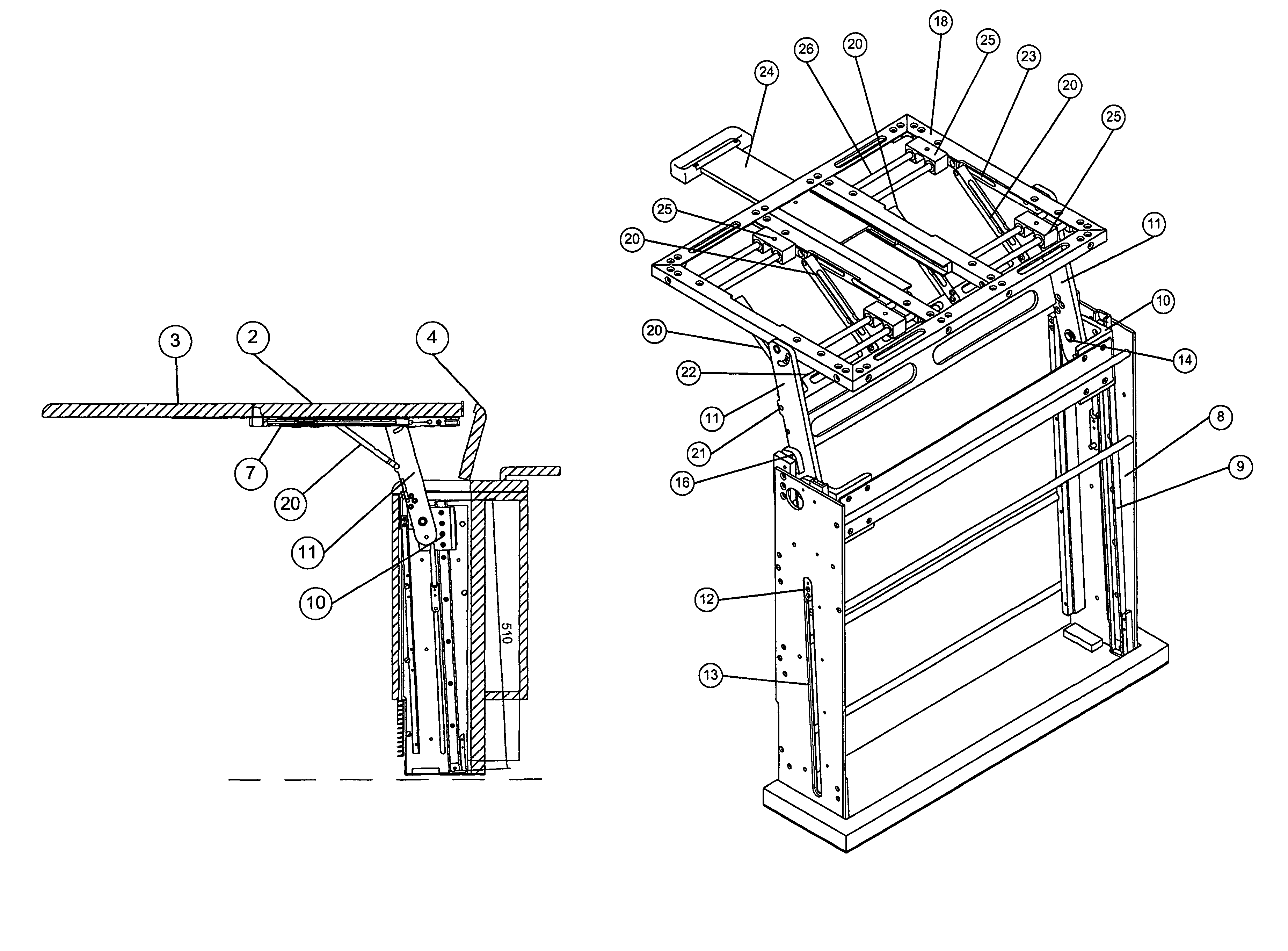
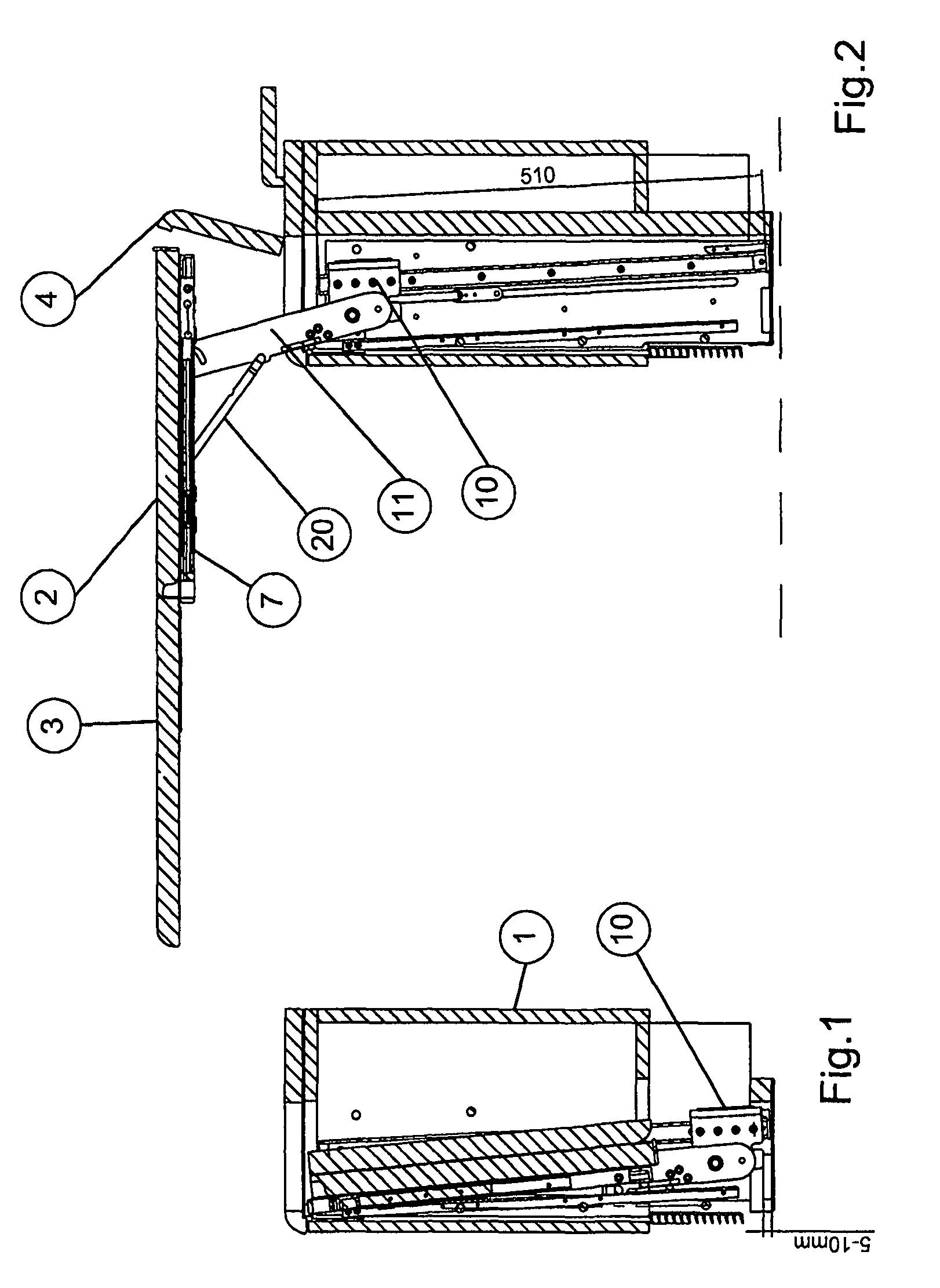
[0038]A table which has two part table tops 2, 3 which can be folded against one another is arranged in a lower housing (credenza) which is denoted overall by 1. In the storage position which is shown in FIG. 1, these tabletops 2, 3 are situated folded on top of one another in the interior of the lower housing 1, at an angle of approximately 3° with respect to the perpendicular.

[0039]FIG. 2 shows the table in the use position. The upper side of the credenza is closed with a lid 4. After the lid has been folded open, the table tops 2, 3 can be pulled out of the credenza. In the use position, the table is held by carrying arms 11 and supporting arms 20 which act on a carrying frame 7, to which in turn the table top 2 is connected.

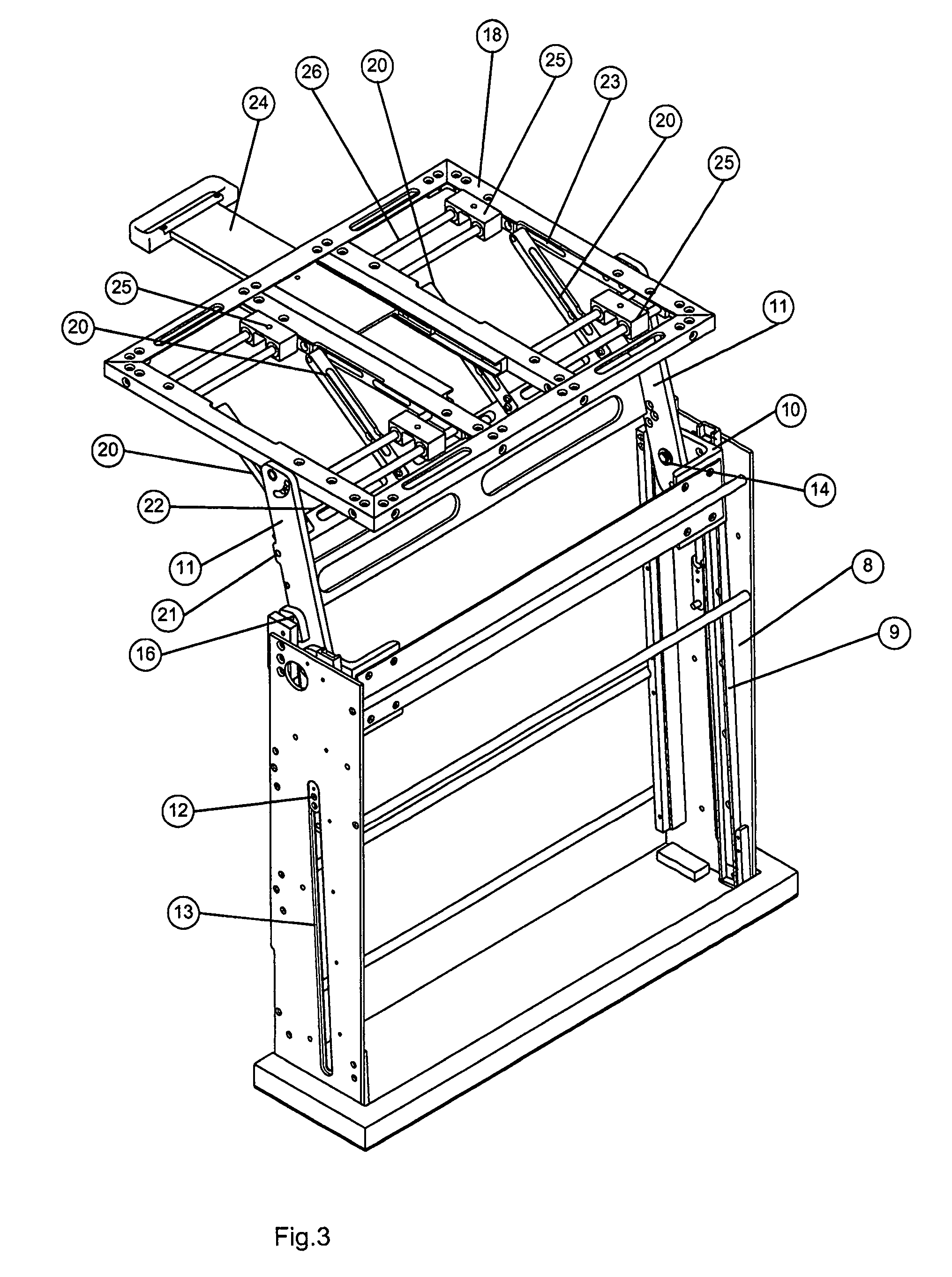
[0040]FIG. 3 shows the carrying frame which is arranged in the credenza, and the carrying mechanics of the table tops including the carrying frame. Guide rails 9 are arranged in the carrying frame which is denoted overall by 8, in which guide rails 9 the slid...


PUM


Abstract

A pivotable table has a lower housing and a table top which can be moved from a storage position, in which the table top is arranged substantially perpendicularly in the lower housing, into a use position, in which the table top is arranged substantially horizontally above the lower housing and is carried by the lower housing. The table includes at least one carrying arm that has an end region which is connected pivotably to the table top and a remote end region which is connected to the lower housing via a carrying arm guide. The table also includes at least one supporting arm, the two end regions of which are connected in each case to the table top and to the carrying arm, at least one of these two connections being of displaceable configuration via at least one supporting arm guide.

Description

REFERENCE TO RELATED APPLICATION[0001]This application claims priority from European Application No. 06 005 897.1, filed Mar. 22, 2006, the entire contents of which are incorporated herein by reference.FIELD OF THE INVENTION[0002]The present invention relates to a pivotable table, having a lower housing and a table top which can be moved from a storage position, in which the table top is arranged substantially perpendicularly in the lower housing, into a use position, in which the table top is arranged substantially horizontally above the lower housing and is carried by the latter.BACKGROUND OF THE INVENTION[0003]In means of transportation, in particular airplanes, storable tables are frequently provided for the passengers. In VIP airplanes and in the first class section of conventional commercial passenger airplanes, a table of this type is usually pulled out of what is known as a credenza, which is arranged next to the seats, and is folded into a use position, in which the table t...

Claims


Application Information

Patent Timeline
Patent Type & Authority Patents(United States)
IPC IPC(8): A47B3/00A47B23/00
CPCA47B5/006B64D11/0638B64D11/06B61D37/006
Inventor CARSTENSEN, SVEN
Owner LUFTHANSA TECH AG
Why Eureka
Try Eureka