LED illuminator

Inactive Publication Date: 2012-01-10
FU ZHUN PRECISION IND SHENZHEN +1
View PDF9 Cites 33 Cited by
  • Summary
  • Abstract
  • Description
  • Claims
  • Application Information

AI Technical Summary

Problems solved by technology

However, in the wild fields, rainwater, moisture, etc., significantly influence a reliability and a lifespan of the LEDs of the LED illuminator.

Method used


Image

  • LED illuminator
  • LED illuminator
  • LED illuminator

Examples


Embodiment Construction

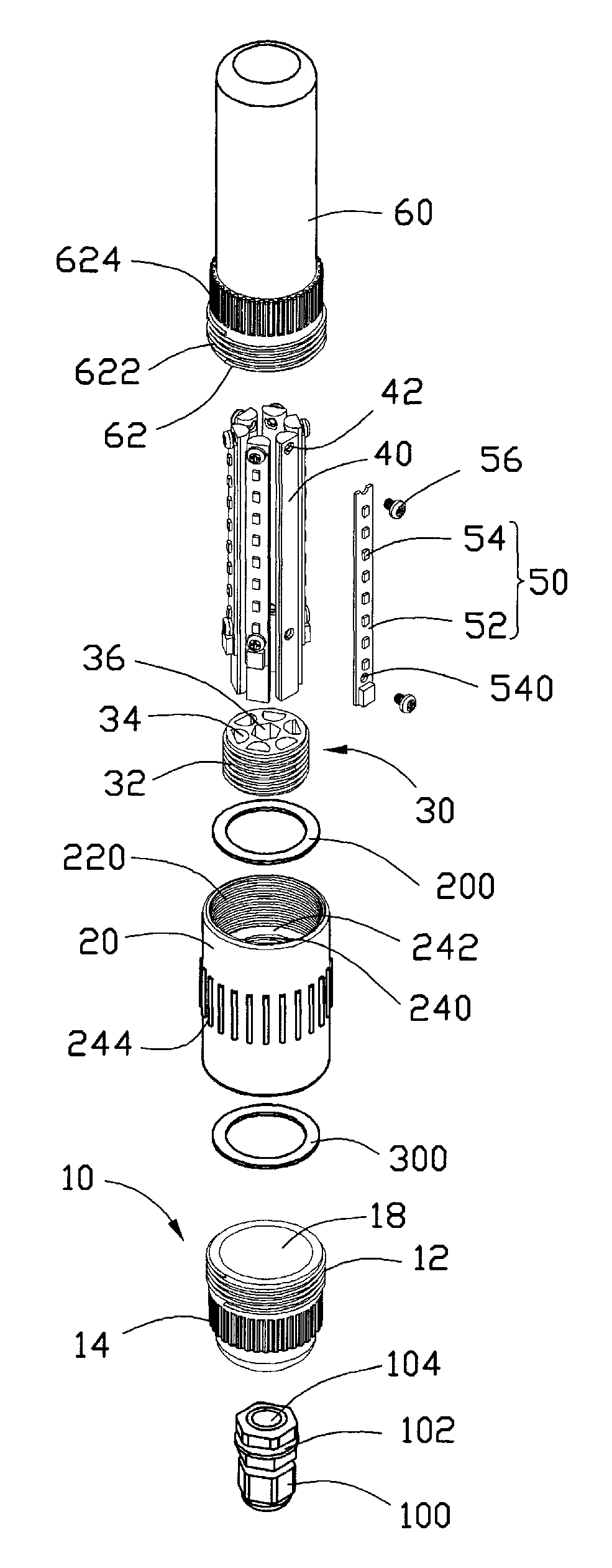
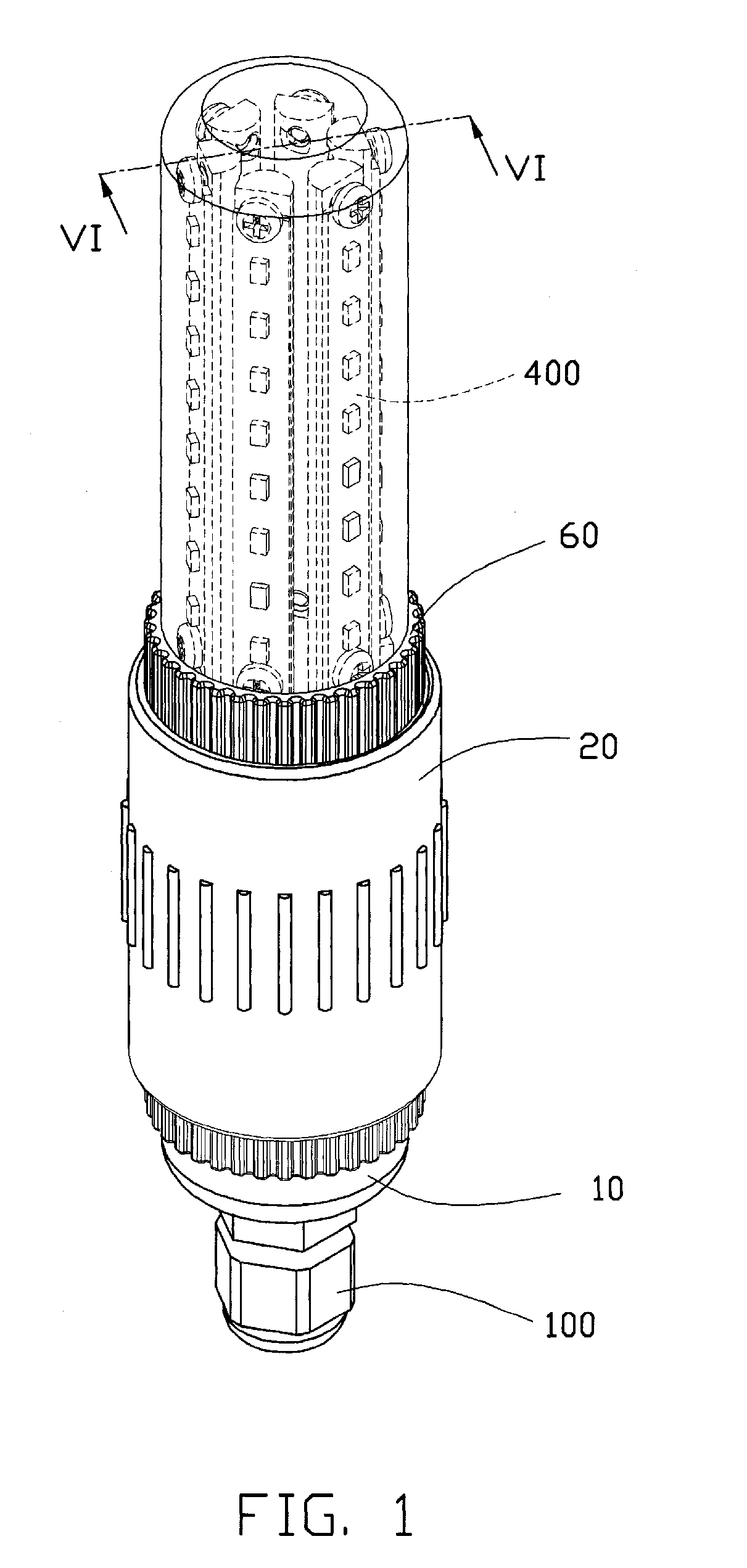
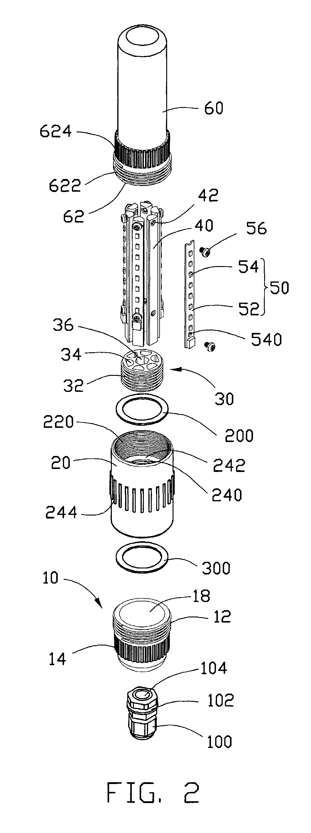
[0013]Referring to FIG. 1, an LED illuminator according to an exemplary embodiment includes a lamp cap 10, a connecting member 20, a light engine 400, a lamp cover 60, and a sealing member 100.

[0014]Referring to FIGS. 2, 3 and 5, the connecting member 20 is cylindrical-shaped, and hollow. The connecting member 20 is made of metal or alloy which has a high heat conductivity coefficient, such as aluminum, aluminum alloy, copper or copper alloy. A plurality of fins 244 are integrally formed on an outer circumferential surface of the connecting member 20. Each of the fins 244 extends along an axial direction of the connecting member 20 with a length thereof being smaller than a length of the connecting member 20. The fins 244 are evenly distributed along a circumferential direction of the connecting member 20, and are substantially arranged at a middle of the connecting member 20 in the axial direction.

[0015]An annular protrusion 24 extends radially and inwardly from an inner circumfere...


PUM


Abstract

An LED illuminator includes a connecting member, a lamp cover, a hollow lamp cap, a plurality of LEDs received in the lamp cover, and a sealing member. The connecting member is a hollow cylinder. The lamp cover couples to and seals a first end of the connecting member. The lamp cap has a top end coupling to a second end of the connecting member opposite the first end and a bottom end defining an aperture. The sealing member defines an annular slot in an outer circumferential surface, with a diameter not smaller than that of the aperture. A portion of the bottom end of the lamp cap around the aperture engages into the slot of the sealing member. A channel extends through the sealing member with a diameter not larger than a conductive wire.

Description

BACKGROUND[0001]1. Technical Field[0002]The disclosure generally relates to illuminators and, particularly, to an illuminator incorporating light emitting diodes (LEDs) as light source.[0003]2. Description of Related Art[0004]LED has an advantage that it is resistant to shock, and has an almost eternal lifetime under a specific condition. Thus LED illuminators incorporating LEDs as a light source intend to be a cost-effective yet high quality replacement for incandescent and fluorescent lamps, particularly in wild fields, such as street lamps, submarine lamps, billboard lamps, and traffic lights. However, in the wild fields, rainwater, moisture, etc., significantly influence a reliability and a lifespan of the LEDs of the LED illuminator.[0005]For the foregoing reasons, therefore, there is a need in the art for an LED illuminator which overcomes the limitations described.BRIEF DESCRIPTION OF THE DRAWINGS[0006]FIG. 1 is an isometric, assembled view of an LED illuminator according to ...

Claims


Application Information

Patent Timeline
Patent Type & Authority Patents(United States)
IPC IPC(8): F21V29/00
CPCF21V19/0055F21V27/02F21V29/83F21V29/777F21L14/023F21L14/026F21V29/004F21Y2103/003Y10S362/80F21K9/00F21Y2101/02F21V29/70F21Y2103/10F21Y2107/00F21Y2115/10
Inventor XIAO, XIN-JIANWUNG, SHIH-HSUN
Owner FU ZHUN PRECISION IND SHENZHEN
Why Eureka
Try Eureka