Surgical drill guide and index system

a drill guide and index system technology, applied in the field of dental prosthesis, can solve the problems of only suitable existing surgical guides, patients cannot create abutments and prosthesis prior to surgery to install implants, and cannot meet the needs of patients who require angled abutments or patients

Inactive Publication Date: 2012-01-31
BAVAR TREVOR
View PDF22 Cites 69 Cited by
  • Summary
  • Abstract
  • Description
  • Claims
  • Application Information

AI Technical Summary

Benefits of technology

[0046]An additional object is to provide a technique and apparatus for design, construction and installation of dental prostheses that is quicker, easier, more accurate, more secure and less expensive than prior art techniques and apparatus.
[0063]The new invention improves over the Rapid Replacement computer aided technique in a variety of ways, including speed, accuracy, ease, convenience and better use of the surgeon's time and less time for the patient in surgery. The computer aided technique is normally used for single prosthesis and / or prosthesis using angled abutments. The new method can utilize the computer system without being so limited, as follows:

Problems solved by technology

A deficiency in this Rapid Replacement method is that it is not suitable for patients who require angled abutments or for patients who need single tooth replacements that require rotational stability via the implant.
When used for the Rapid Replacement Method, the existing surgical guides are only suitable for screw retained prostheses where multiple straight abutments are used.
Computer generated guides can still be used for angled abutments or single tooth replacement, but the abutments and prosthesis cannot be created prior to the surgery to install the implants.

Method used


Image

  • Surgical drill guide and index system
  • Surgical drill guide and index system
  • Surgical drill guide and index system

Examples


first embodiment

[0117]the new surgical guide 40 is shown schematically in FIG. 2a, having a mouth side or exposed side 40A of base part 41. Drill guide sleeves 42 are positioned and oriented optimally in regard to the bones to receive implants, and guide holes 43 are provided for receiving nail or other fasteners to temporarily secure the surgical guide to the mouth for the drilling and implant installation procedure.

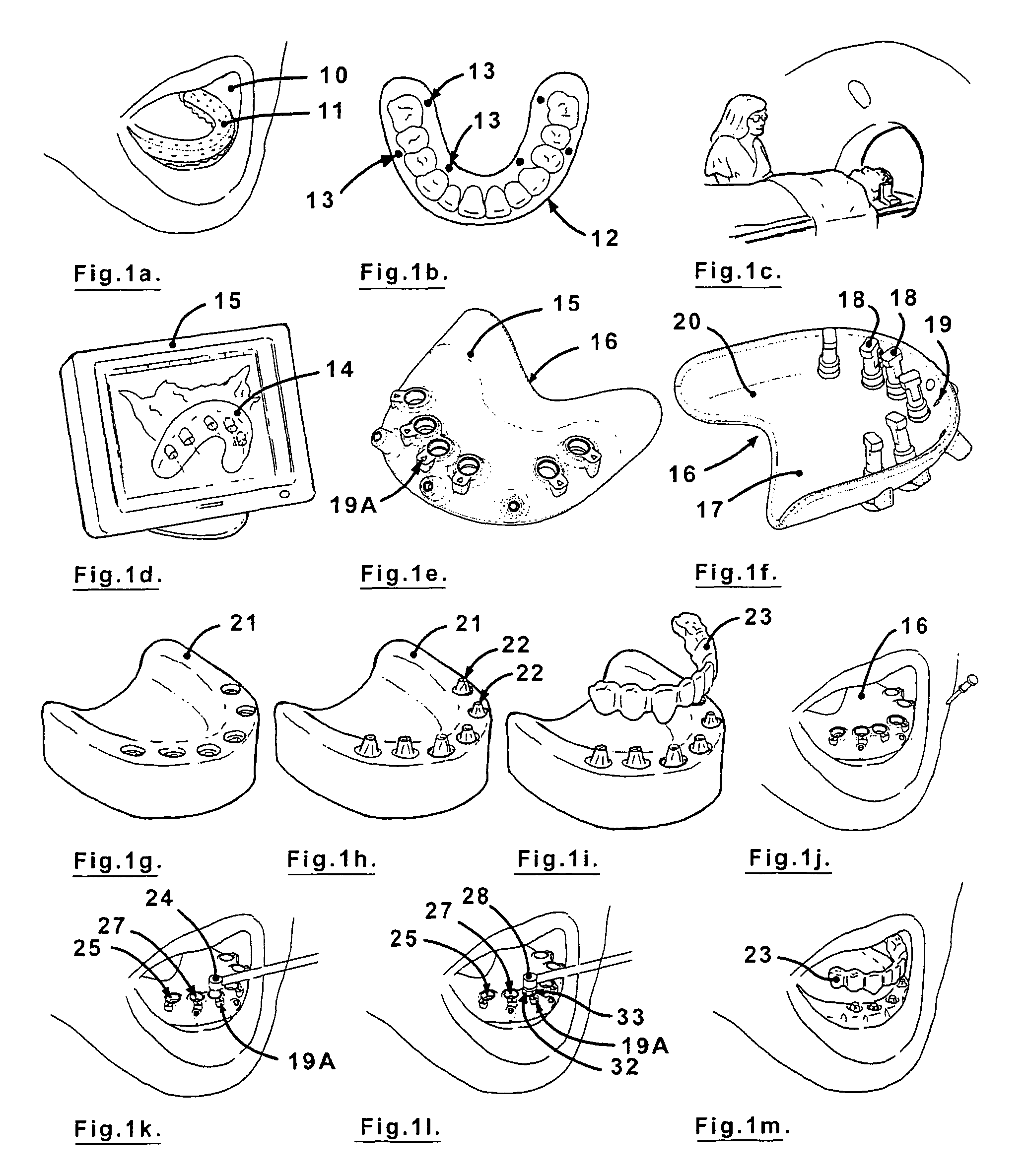
[0118]FIG. 2b shows an analog assembly 44, and FIG. 2c shows an exploded view of said analog assembly. This assembly consists of analog 45, analog mount 46 and attachment screw 47. The analog 45 of FIGS. 2b and 2c is typical of the analogs that would be attached to surgical guide 40 in FIG. 2a, which is then used to create a model of the type shown in FIGS. 1f-1h on Sheet 1.

[0119]As seen in FIGS. 2a-2c the new invention provides rotational markings 46A on the analog mount 46 and corresponding marks 48 on the surgical guide. In the subsequent stage each analog is positioned in a guide s...

embodiment 90

[0131]FIG. 7 illustrates a further drill guide embodiment 90 similar to drill guide 80 of FIG. 6, except that grooves 82 in the guide and keys 85 on analog mount 84 in FIG. 6 are replaced by keys 91 in the drill guide 90 and grooves 92 in the analog mount 93 respectively in FIG. 7.

[0132]A still further surgical guide embodiment similar to that of FIGS. 4a and 4b, has the same general structure, but is transparent so that a rotational position indicator on one side (tissue or mouth side) can be seen from the other side, and thus marks are not required on both sides. Such an embodiment will be defined as (a) having a rotational position indicator on said mouth side or (b) having a rotational positional indicator on at least one of said moth and tissue sides, and discernable on the other side. FIGS. 43a and 4B show the marks on the mouth side.

[0133]FIG. 8 shows various different drill guide sleeve embodiments, 1-8, each having coordinated rotational position marking on internal and ext...


PUM


Abstract

A surgical drill guide for installing dental implants with predetermined angular alignment and rotational orientation for a dental prosthesis, formed of: a. a base part formed to correspond generally to the shape and contour of a patient's upper or lower mouth, the base part having peripheral edges and having opposite tissue and mouth sides and at least one drill guide hole extending through the base part from the tissue side to the mouth side, each of the drill guide holes having a central axis at a predetermined angular orientation relative to the mouth side and having lateral location relative to the peripheral edges, and b. a set of rotational position indicators on the tissue and mouth sides respectively of the base part for each of the drill guide holes, the rotational position indicators of each set being at the same rotational position about the central axis of the drill guide hole.

Description

[0001]This application claims priority on Provisional Application No. 60 / 931,901 filed May 25, 2007 which is incorporated by reference herein.I. BACKGROUND OF THE INVENTION[0002]A. Field of the Invention[0003]This invention is in the field of dental prostheses and methods and apparatus for manufacturing dental prostheses and for installing dental prostheses in a patient's mouth.[0004]B. Prior Art Patents and Publication[0005]“NobelGuide—Procedures & Products Powered by Procera®”©Nobel Biocare Services AG 2005,[0006]U.S. Pat. Nos. 5,595,703; 5,768,134; 6,361,318; 6,821,123; 6,848,909; and 6,902,401.[0007]C. Prior Art Procedures and Apparatus[0008]1. In describing prior art procedures and apparatus the following terminology and definitions are commonly used.[0009]Dental Prosthesis means an artificial tooth or a series of artificial teeth that is used to cosmetically and functionally restore missing or damaged teeth in a patient.[0010]Implant means a structure that is implanted in a pa...

Claims


Application Information

Patent Timeline
Patent Type & Authority Patents(United States)
IPC IPC(8): A61C19/04A61C3/00
CPCA61C1/084
Inventor BAVAR, TREVOR
Owner BAVAR TREVOR
Why Eureka
Try Eureka