Display panel apparatus

a technology for display panels and apparatuses, applied in the direction of printed circuits, circuit arrangements on conductive chasms, instruments, etc., can solve the problems of abnormal image display, inability to withstand external force, frequent external impact of lcd modules, etc., to prevent the flexible printed circuit from being peeled or broken, improve the connection structure of the circuit board, and effectively reduce the stress concentration

Active Publication Date: 2012-01-31
AU OPTRONICS CORP
View PDF10 Cites 1 Cited by
  • Summary
  • Abstract
  • Description
  • Claims
  • Application Information

AI Technical Summary

Benefits of technology

[0008]In order to resolve the above problems, the present invention provides a display panel apparatus with improved connection structure of the circuit board to effectively decrease stress concentration caused by the flexible printed circuit itself or the soldering area connecting to the circuit board, thereby preventing the flexible printed circuit from being peeled or broken and improving the quality and durability of the display panel.

Problems solved by technology

This type of LCD module frequently suffers external impact during assembly and transportation, and if the FPC is not secured by screws it cannot withstand the external force.
Such PFC peeling causes an abnormal image display.
When the stress exceeds a threshold, the FPC will be peeled or broken, resulting in degraded signal transmission.

Method used


Image

  • Display panel apparatus
  • Display panel apparatus
  • Display panel apparatus

Examples


Embodiment Construction

[0020]The making and use of the presently preferred embodiments are discussed in detail below. It should be appreciated, however, that the present invention provides many applicable inventive concepts that can be embodied in a wide variety of specific contexts. The specific embodiments discussed are merely illustrative of specific ways to make and use the invention, and do not limit the scope of the invention.

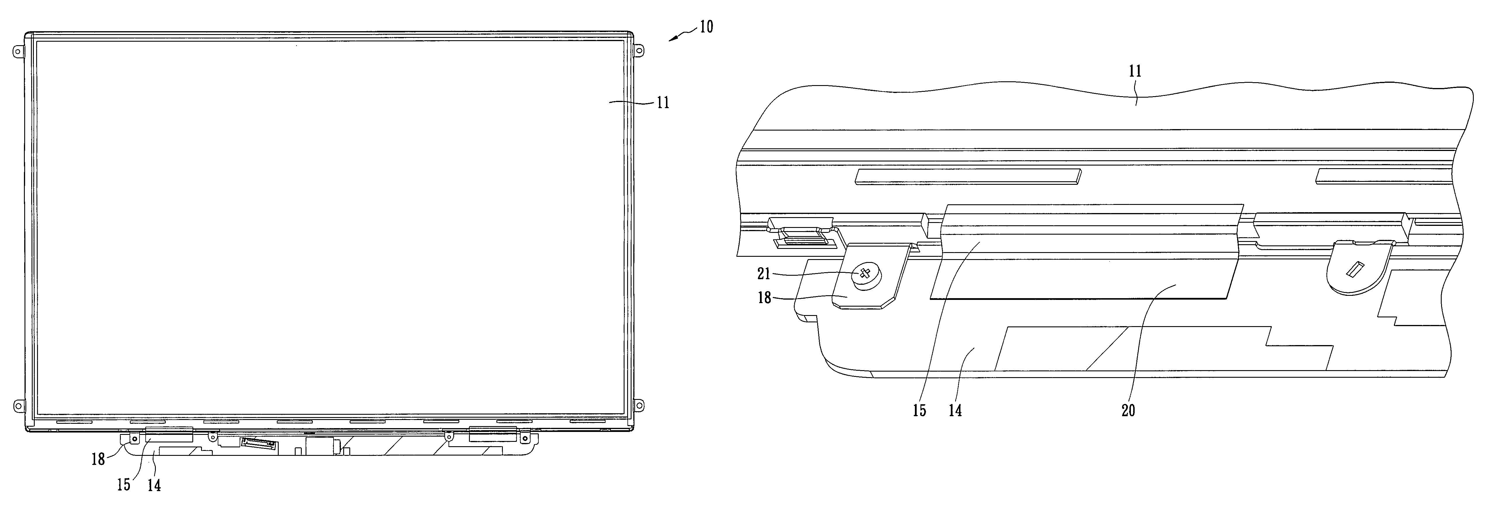
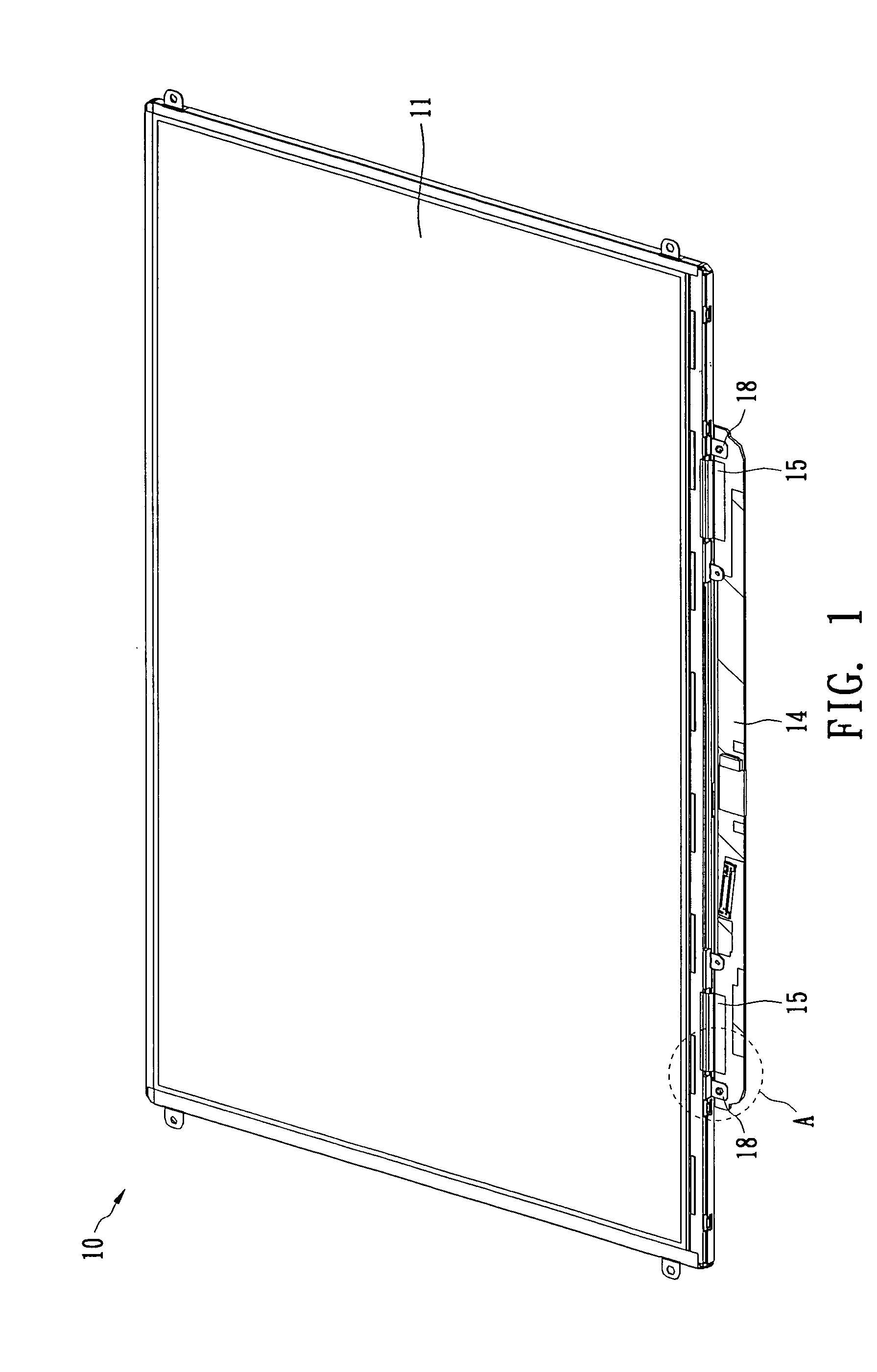
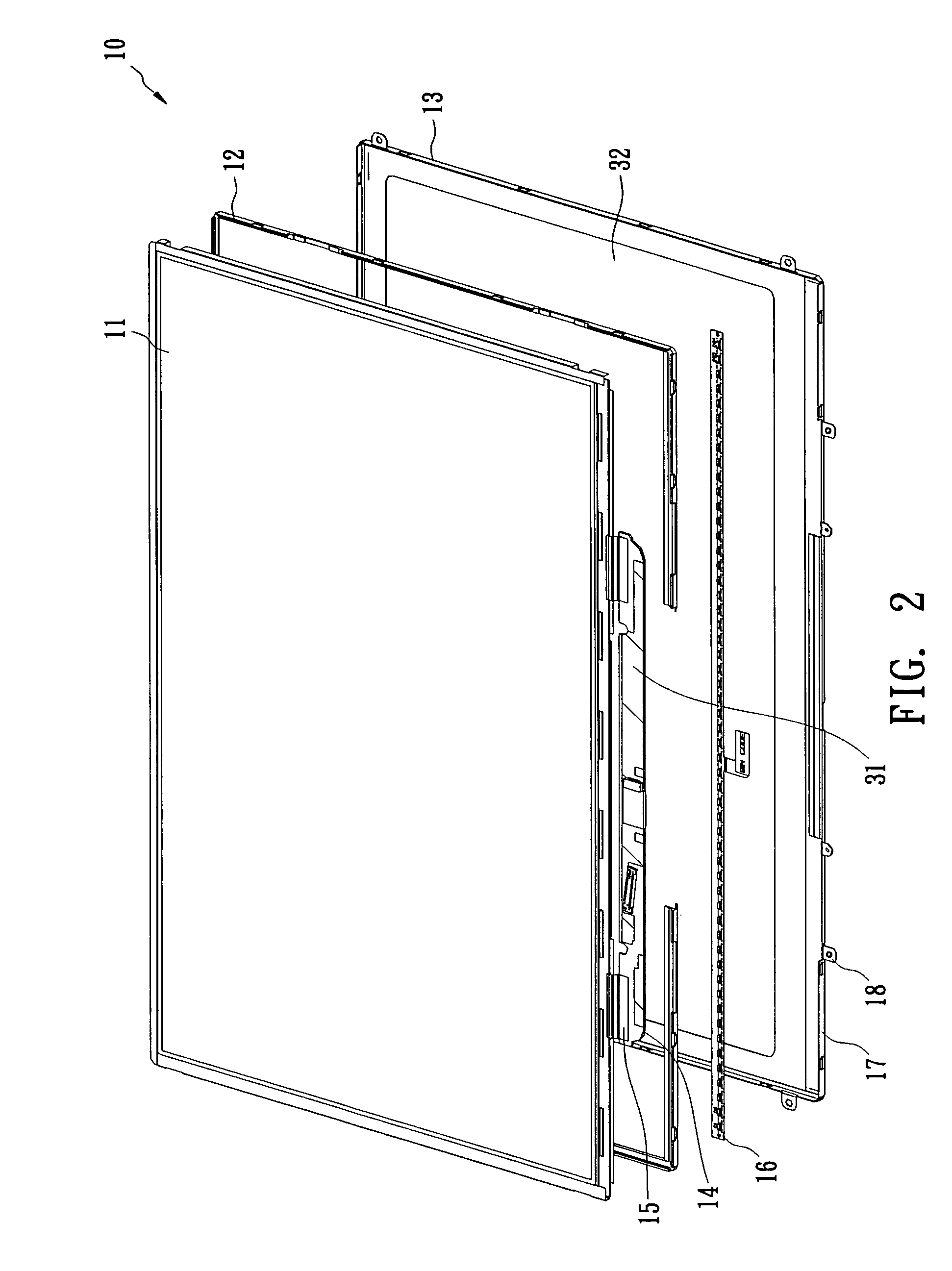
[0021]FIG. 1 shows a display panel apparatus 10 in accordance with an embodiment of the present invention. FIG. 2 shows an exploded view of the display panel apparatus 10. FIG. 3 shows the top view of the display panel apparatus 10. FIG. 4 shows the magnification view of the area “A” of FIG. 1. The display panel apparatus 10 includes a display panel 11, a sealant 12, a back bezel 13, a circuit board 14 and FPCs 15. The sealant 12 and the bezel 13 are disposed at the rear of the display panel 11 in sequence, and the bezel 13 includes two fixed portions 18, e.g., tabs, extending ...


PUM


Abstract

A display panel apparatus includes a panel, a fixed frame, a circuit board and one or more flexible printed circuits (FPC). The fixed frame may be a back bezel or a frame, and is placed at the rear of the panel. The fixed frame includes two fixed portions extending outwards from a side thereof. The circuit board is connected to the two fixed portions and disposed at the side of the fixed frame, and extends away from the fixed frame. The maximum plane of the circuit board and the maximum plane of the fixed frame are disposed at a same (common) plane. More specifically, the maximum plane of the circuit board and the maximum plane of the fixed frame are not overlapping in a vertical direction, and are on a same horizontal plane.

Description

BACKGROUND OF THE INVENTION[0001](A) Field of the Invention[0002]The present invention relates to a display panel apparatus, and more specifically, to a display panel apparatus having an improved circuit board connection structure.[0003](B) Description of Related Art[0004]Liquid crystal displays (LCD) have many advantages such as thin profile, light weight, low power consumption and low radiation, and therefore are widely used in current display applications. An LCD display primarily includes an LCD panel and a back light unit. The back light unit serves as an illumination source to the LCD panel, and the rotations of the liquid crystals are controlled by electrical signals so as to display images.[0005]An LCD panel includes a display panel and a circuit board placed at a side of the display panel, and a flexible printed circuit (FPC) connects the display panel and the circuit board as a signal transmission interface. Generally, the circuit board and the display panel are not on the...

Claims


Application Information

Patent Timeline
Patent Type & Authority Patents(United States)
IPC IPC(8): H05K1/00
CPCG02F1/133308G02F2001/133314G02F2201/46H05K1/147G02F1/133314
Inventor TSAI, CHENG MINCHENG, CHING HUNGCHENG, HAN CHANG
Owner AU OPTRONICS CORP
Why Eureka
Try Eureka